A TREATISE ON THE SCREW PROPELLER : with various suggestions of improvement
London; Longman, Brown, Green and Longmans ; 1852
by John Bourne, C.E.
CHAPTER I. - HISTORICAL ACCOUNT.
I propose to devote this Chapter to the recapitulation of the various projects which have been propounded at different times for propelling vessels by means of a screw. I shall endeavour to trace, so far as now seems practicable or useful, the earlier history of this contrivance, and shall also inquire to whom, among the various inventors whose works pass. under review, the practical realization of the idea of screw propulsion is properly attributable. Successful invention generally implies the existence of two distinct kinds of merit. The one lies in the conception or discovery of eligible expedients of improvement; the other lies mainly in the diligence and persistency necessary to remedy the crudities of a first essay, to dispel the doubts of the unbelieving, and to overcome the inertia by which new projects are obstructed. The latter species of merit has, in most cases, the largest claim upon the public admiration, for its successes are both more difficult and more rare than those of mere abstract invention; and since it is only from the practical realization of a mechanical idea that any advantage to the public is obtained, and since also the rights of inventors rest upon reciprocity of advantage between themselves and the public, it is clear that the validity of patents should only be recognised where a public benefit has been conferred. In those cases, however, the recognition of a valid title should be prompt and unequivocal, nor should any alternative condition be permitted between that of a title past question and that of no title at all.
The screw propeller is, in all probability, a very ancient contrivance. In China it is said to have been known for ages; but in European countries the idea of a screw propeller appears to have been derived either from the windmill or smoke-jack, or from the screw of Archimedes, —an instrument much used in some countries for raising water. The windmill and smoke-jack appear to be both ancient contrivances. In the 77th proposition of Hero’s “Spiritalia,” a work written 130 years before the Christian era, a windmill, of a construction similar to those now in use, is represented as applied to blow an organ, the air being forced into the air-chest of the organ by means of a cylinder and plunger or piston, worked by the windmill. In the East the windmill was used in ancient times for raising water for purposes of irrigation. Christie, in his account of Seistan, a district lying to the east of Persia, and watered by the Helmund, says, “ The country, though now only inhabited by Afghans and Beloochees in felt tents, still bears the marks of former civilisation and opulence; and there are ruins of villages, forts, and windmills along the whole route, from Rodbar to Dooshak.”Seistan is celebrated as the ordinary residence of Rustum, of romantic celebrity among the Persians. It was conquered in 1883 by Tamerlane, who exterminated the inhabitants, and reduced the towns to ruins.* [* See Thornton's Gazetteer of the Countries adjacent to India. Allen & Co, 1844.]
The smoke-jack is substantially a small windmill, driven by the current of air or smoke ascending a chimney. Chimneys are supposed by some persons to be a comparatively modern invention, and to have been introduced into this country about the reign of Elizabeth. But this opinion is certainly erroneous; for houses built long before the time of Elizabeth, and furnished with chimneys, which are manifestly part of the original structure, may still be met with at Southampton and elsewhere. In Coningsburg Castle, in Yorkshire, supposed to have been built by W. de Warrein in the year 1070, a chimney of very excellent construction occurs, and this chimney is so built up in the castle walls that it could not have been a subsequent addition. In the houses of the Greeks and Romans, chimneys appear to have been but little used; and in Spain, Barbary, and throughout a large part of the East, chimneys are but little used in the ordinary class of houses at the present day,—a fire being seldom needed for purposes of warmth, and the operations of cookery being, for the most part, performed by means of an open charcoal fire. Nevertheless, in some of the houses of the Greeks and Romans, chimneys did exist, and references to these chimneys may be found in ancient authors. The hypocausta, or stoves, by which the superior class of houses were warmed in cold weather, had necessarily chimneys; the furnaces of the baths had also chimneys, as had also the camint, or metallurgic furnaces, from which the word chimney appears to have been derived. Houses in which wood was burnt must necessarily have had chimneys of some kind to let out the smoke, and in ancient times large quantities of fire-wood were sold at Rome. And where chimneys existed, the introduction of a small windmill into them to take advantage of the upward current of air, was too obvious an expedient not to have been attempted at a very early period, though at what time the application was first made there is now no means of ascertaining. The chimneys of the ancients were for the most part of imperfect construction, and the houses were consequently smoky. The best kind of fire-wood was scorched before being exposed for sale.
There appears very little doubt that windmills were in use among the Romans, as affirmed by Pomponius Sabinus ; and by an old Bohemian chronicle * [ * Wenceslai Hagecii Chronic. Bohem. Translated into German by John Sandel. Nuremberg, 1697.] it appears that no mills but windmills were in use in that country before 718, at which time a watermill was first introduced. The knowledge of the windmill was probably brought into Western Europe by the Crusaders; and soon after the Crusades began, charters were granted to parties in France and England authorising the construction of windmills. In Holland, windmills were largely introduced for draining the land; and in order to make them available with every wind, they were set upon floats, which could be turned round, so that the sails would face the wind from whatever quarter it came. Subsequently other expedients were adopted for the accomplishment of this object, some of which are still employed.
It is now pretty certain that boats propelled by paddle-wheels moved by oxen were used both by the Carthaginians and the Romans; and in 1543, Blasco de Garay, a Spanish sea-captain, appears to have succeeded in giving motion to wheels of this kind by means of steam, though the arrangements he adopted are unknown, and no practical benefit resulted. In 1618, and again in 1630, David Ramsey obtained patents in this country for methods of making vessels go against wind and tide. In 1632, Thomas Grent obtained a patent for enabling becalmed ships to make a speedy passage ; and in 1637, Francis Lin obtained a patent for “ drawing and working up barges and other vessels” without the aid of horses. In 1661, the Marquis of Worcester obtained a patent for a species of vessel which would ascend a rapid in a river, by rendering available the force of the stream for the upward propulsion of the vessel; and in the same year a patent was granted to Thomas Toogood and James Hayes for the propulsion of vessels by forcing water out through the bottom. Papin, Savery, Allen, Hulls, and others, subsequently proposed a variety of arrangements for propelling vessels by a steam engine giving motion to paddle-wheels, and this object became readily accomplishable so soon as Mr. Watt’s improvements upon the steam engine enabled a rotatory motion to be obtained from it with advantage.
ROBERT HOOKE. Born, 1635; Died, 1703.
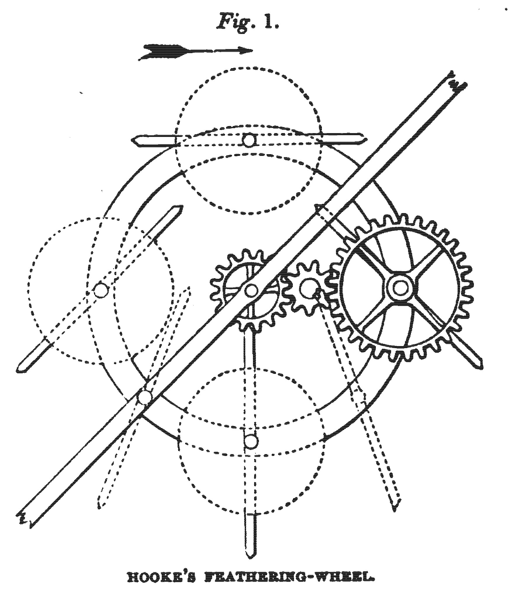
A windmill with four vanes is substantially a screw with four threads [1], and as a windmill is an ancient contrivance, a screw must also be so, only that in the case of a windmill the arms work in air instead of in water.’ The idea of making a screw on the plan of a windmill, to work in water, appears to have originated with Robert Hooke, one of the most remarkable men this country has ever produced. In a work, entitled “Philosophical Collections,” printed for Richard Chiswell, printer to the Royal Society, 1681, there is a paper by Hooke on Horizontal Windmills, containing, as all his papers do, many valuable suggestions on various subjects. Hooke says that he does not believe horizontal windmills to be as good as vertical windmills; but that if horizontal windmills are in any case employed, it will be advisable to adopt a form which he suggests, as preferable to any heretofore recommended, and which is represented in fig.1. Hooke says that there are certain first principles common to the sails both of windmills and ships, which it is important should not be transgressed, if an efficient performance is required; and of these the first is, that the vane or sail upon which the wind impinges shall be, as far as possible, a perfect plane, without any bellying, bunting, or curvity, such as is often to be met with in the sails of ships, and which nautical men commonly reckon as an advantage. The second of these first principles is, that the air shall have as many passages between the parts of the vane or sail as can conveniently be provided, so that the moving air may impinge on the surface of the sail freely, without being obstructed or intercepted by stagnant air in front of it. The third of these first principles is, that the plane of the vane or sail shall be put in the middle inclination, between the way of the wind and the way of the arm, or that of the body of the ship. It will be seen from the figure, that the wooden vanes of this horizontal windmill turn upon a centre, in the same manner as the feathering floats of modern padble-wheels. The motion of these vanes or floats is governed by means of gearing; but Hooke says that this is not the best expedient for the purpose, and that he has only introduced toothed wheels into the diagram, because their action is readily comprehended.
While, however, Hooke disapproves of the substitution of this horizontal windmill for the vertical windmill commonly employed, he thinks the expedient“ may be of great use for watermills in rivers where there can no dam be made, as may also the perpendicular vanes of other mills; which,” he adds, “I thought also not inconvenient to mention by-the- bye, neither of them being so much as hinted by any person whatever that I have hitherto heard of.”
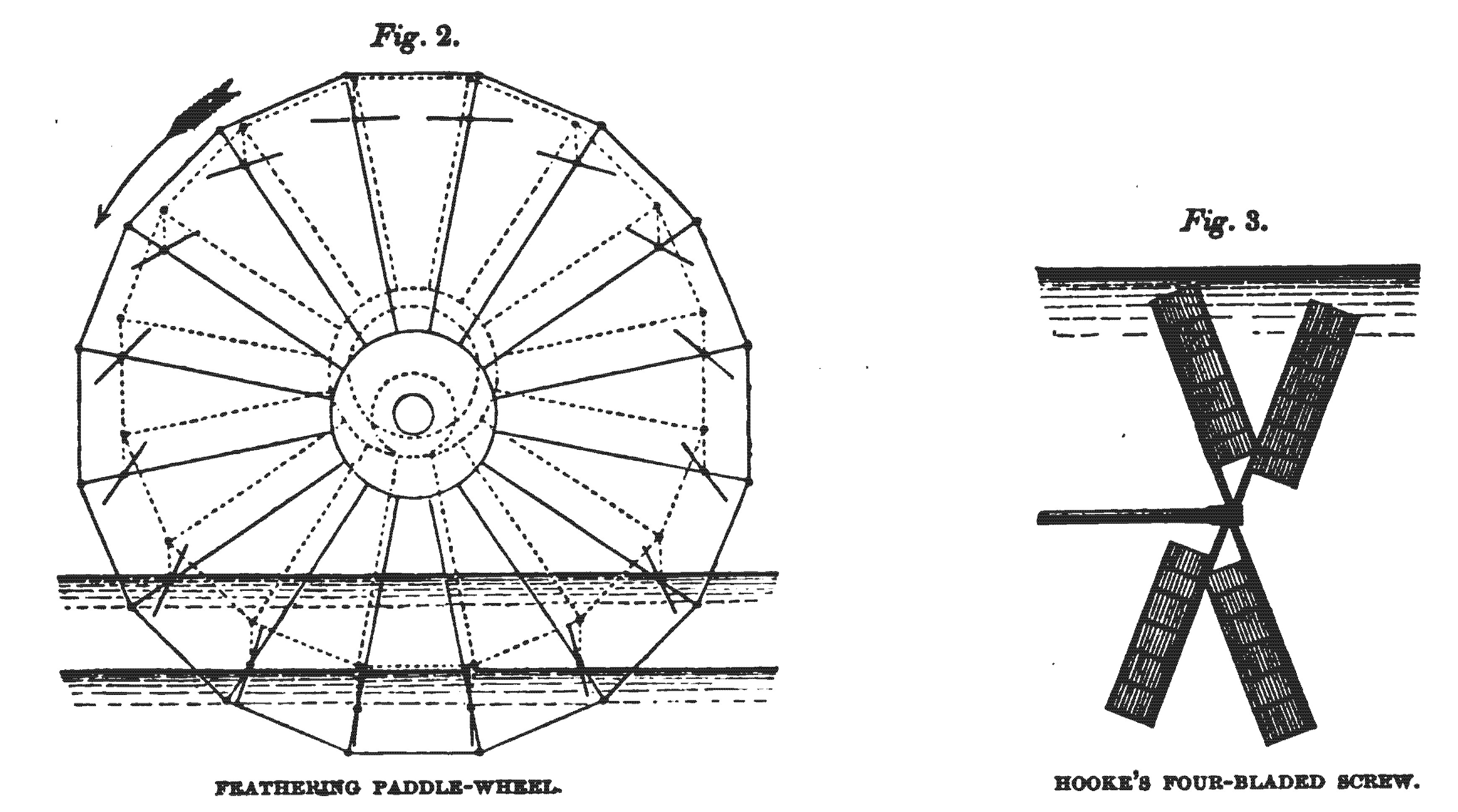
In this rapid outline we have all the main features, both of the screw propeller and feathering-wheel, in-their most efficient form. For no screw propeller is more efficient than a screw with four arms, like the vanes of a windmill; and, in the best feathering-wheels, the plane of the float-board passing through the water is put in the middle inclination, between the way of the arm and the way of the stream, as Hooke recommends should be done. In these arrangements, it is true, the water drives the screw or paddle-wheel, instead of being driven by it; but it is obvious that the one problem is just the reciprocal of the other, and the same considerations which make the arrangements proposed eligible in the one case, also make them eligible in the other, fig.1. is copied from a woodcut given in the “Philosophical Collections ;” fig. 2. represents a paddle-wheel constructed on Hooke’s principle, and which is identical in all material points with that known as Oldham’s paddle- wheel; and fig. 3. represents a screw of the windmill form, operating in water, after the manner that Hooke proposed.
On the 14th November, 1683, Hooke showed to the Royal Society an instrument he had invented for measuring the velocity of the wind. It consisted of four vanes, like the vanes of a windmill, set upon an axis, and made very light and easy of motion. The vanes were so contrived, that they could be set at any slope or angle that was desired, and the rate of the instrument could be thereby varied so as to enable any adjustments to be made that were requisite to give exact indications. This instrument was tried in the long gallery in Gresham College, and its operation was found to be satisfactory. On the 28th November, 1683, Hooke showed to the Royal Society an instrument he had contrived and shown to some of the members twenty years before, by which the way of a ship through the water, or the velocity of a river, could be measured. This instrument, of which the most essential part was & screw turned by the water, was designed, not merely to keep an account of the distance run, but also of the amount of lee-way under all the tackings of the ship. Only the vane or fly of the instrument was shown to the Society, and it appears to have constituted the original of the patent or Massey’s log, now coming into use; but Hooke’s instrument was more perfect than the present patent logs, as it took cognizance of the lee-way. Hooke had also, it is understood, discovered a method of enabling his log to take cognizance of ocean currents, which no existing instrument can do; and he is also said to have discovered a method of constructing an instrument capable of tracing upon a map or sheet of paper the course of a carriage on a road, whatever windings it might make: but these, with many of his other inventions, are now lost. The plan of making gearing in steps, as is done in nearly all screw vessels in which gearing is employed, is an invention of Hooke’s, as is also the revolving pendulum, the universal joint, the application of the balance-spring to watches, and numberless other inventions of great originality and importance. He also appears to have been the first person who arrived at just ideas touching the nature of combustion, and his doctrines Lavoisier only revived ; he traced the phenomena of the tides to the attraction of the moon, and had a clear apprehension of the universality of the principle of attraction, and the important part it plays in the system of the universe ; he predicted that the earth would be found to be flattened at the poles, and that the rate of clocks would be found different near the poles from the rate near. the equator. In optics, geology, and most other depart- ments of physics, he made important discoveries or suggestions ; and many of the ideas which Newton worked out, were previously entertained by Hooke, though Newton appears also to have arrived at them by an independent process.
Much misconception still exists regarding the manner of propelling and guiding the galleys of the ancients. It appears, from the account given by Suidas, that they had sometimes a rudder at each end, so that they might be propelled either way without difficulty; and Atheneus, in his Fifth Book, says that Ptolemy Philopator’s great ship was “biprora et bipuppis,” or, in other words, a twin vessel. Hooke, in a very interesting lecture on the method of rowing the ancient galleys, delivered in July, 1684, propounds the following opinions :—
First, that the oars used by the ancients were very much like the oars used by us, but broader and flatter, shorter and lighter, and managed only by one or two. Secondly, that they were moved, not vibrating backwards and forwards as ours now are, but inwards and outwards, so that the action rather resembled sculling than rowing. Thirdly, that they did not lie horizontal as ours do, but almost perpendicular; and when aground, the oars served as legs or props to sustain the vessel. Fourthly, that they were not lifted out of the water, but always remained immersed. Fifthly, that they always promoted the vessel, whether they were moved outwards or inwards; and sixthly, that the rowers did seldom sit with their faces to the poop of the vessel, but sometimes with their faces toward the prow, and for the most part with their faces outwards and forwards. He also mentions in what way he considers the rowers must have been distributed, and concludes that, in the larger vessels, there must have been considerable overhang of the sides to enable the several tiers of rowers to work simultaneously. The rowers, by a sculling action, moved their oars altogether, either outward or inward, and, by this mode of propulsion, great velocity of motion might, it was considered, be attained. In modern boats with horizontal oars, the action resembles that of a paddle-wheel; whereas, in the ancient galleys, the sculling action more resembled that of a screw, which is, in effect, a continuous sculling machine, in which the necessity of a reciprocating movement is superseded, by giving a complete revolution to the pro- pelling blade.* [* : See Waller's Posthumous Works of Robert Hooke, p. 569. London. Folio, 1705.]
LEUPOLD. 1724.
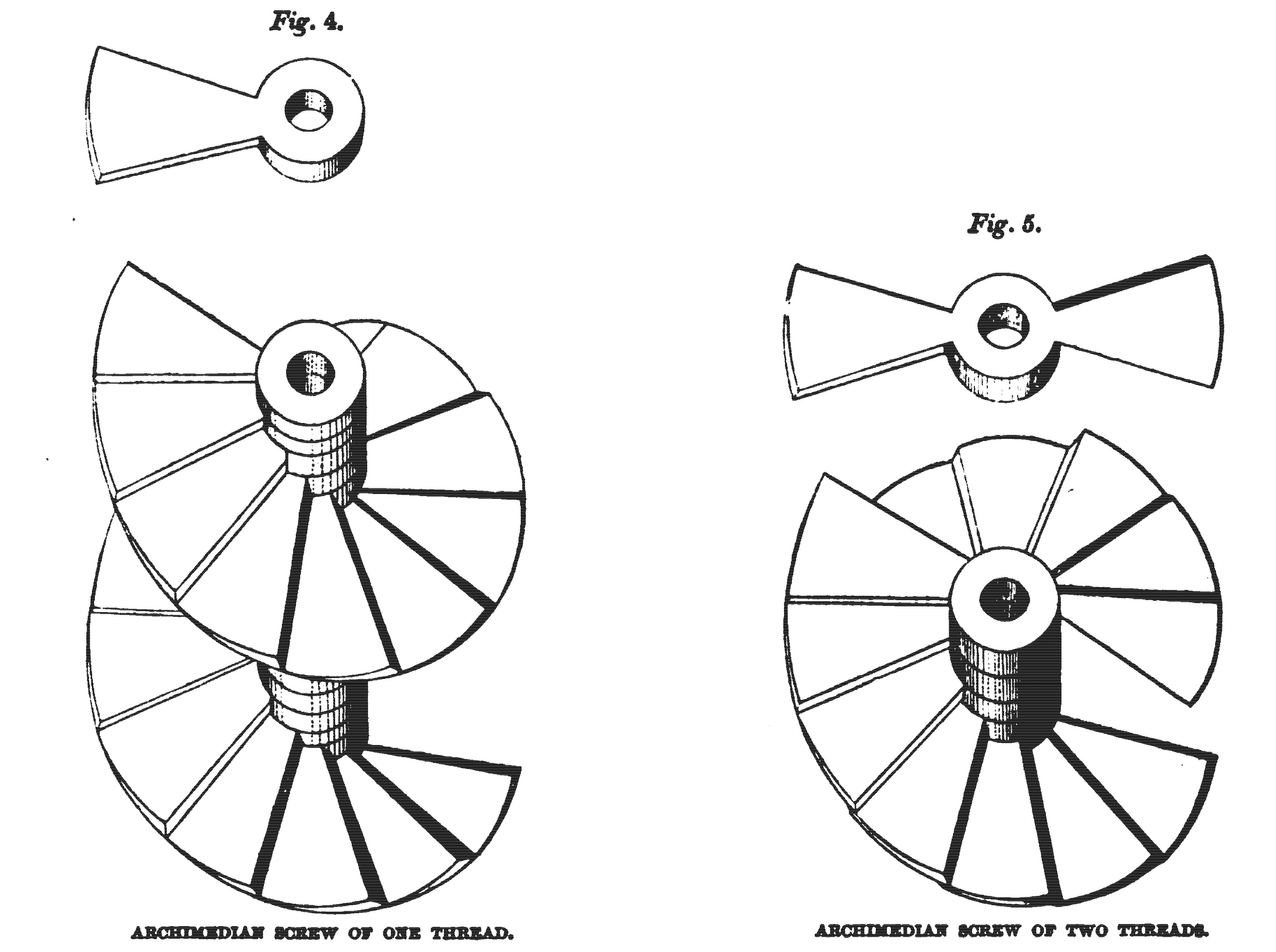
Leupold, in his “Theatrum Machinarum,” gives drawings of several arrangements of Archimedian screws driven by windmills for raising water from low lands. Figs. 4. and 5. are copied from this work; fig. 4. being a portion of an Archimedian screw with a single thread, and fig. 5. a portion of an Archimedian screw with a double thread. The upper portion of fig. 5. bears a near resemblance to a screw propeller such as is now commonly employed. These screws are termed “water snakes” in Holland. The existence of this species of screw is probably traceable to a much higher antiquity than the time of Archimedes, though it is now commonly called by his name.
DU QUET. 1731.
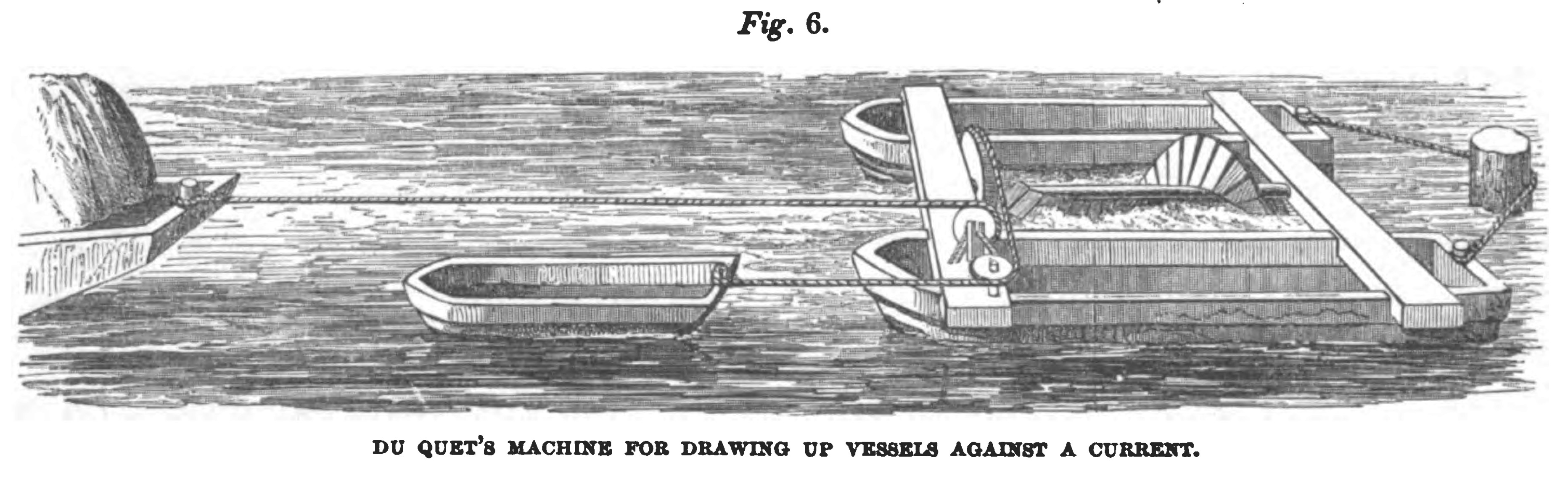
In the “Recueil de Machines approuvées par l’Academie,” tome i., there is an account of an arrangement of revolving oars, invented by M. Du Quet, in which four oars set in an arbor are made to revolve like a paddle-wheel, and the emerging float is feathered by being turned edgeways to the water in its ascent. This plan was tried at Marseilles in 1693, by order of Louis XIV., and was also tried at Havre. It was said to give better results than the oars of a common galley, and was approved by the Academy in 1702, but has never been found to be of any utility in practice. In the “Recueil de Machines approuvées par l’Academie depuis 1727 jusqu’au 1731,” another contrivance by Du Quet is given for dragging vessels up against a stream, by means of a screw, or helical feather, which is turned round by the water. This contrivance is represented in fig. 6., and it is obviously very inferior in efficacy to the previous project of Hooke, in which a four-bladed screw, resembling the vanes of a windmill, is completely immerged in the running water, instead of dipping superficially, in the manner of Du Quet’s machine.
DANIEL BERNOUILLI. 1752.
In 1752, Daniel Bernouilli obtained the prize offered by the French Academy of Sciences for the best project for impelling vessels without the aid of wind. He proposed to employ inclined planes, acting obliquely upon the water, as in the ancient galleys, but those planes were to move circularly, like the vanes of a windmill. The advantages of the sculling mode of propelling, as practised by the ancients, had previously been pointed out by Hooke, as well as the efficiency of vanes, like those of a windmill, working in water; and Bernouilli proposed to apply two or three wheels with inclined paddles, resembling the vanes of a windmill, on each side of a vessel, and two more at the stern. These wheels, or screws, were to be about 6 ft. in diameter, they were to be completely immerged in the water, and were to be moved either by steam engines or by horses.
W. EMERSON. 1754.
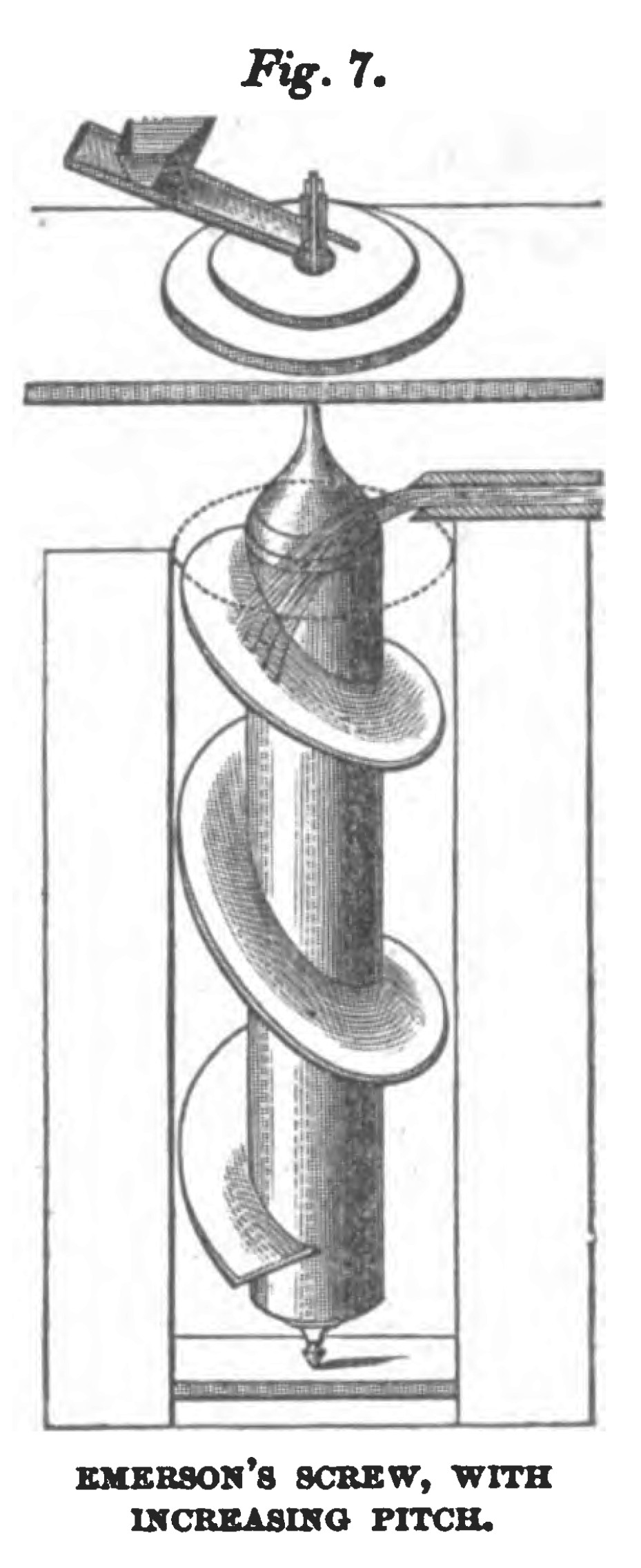
Wheels impelled by the gravity of water acting upon oblique vanes, set in a conical casing, have been long used in France under the name of Danaides, or rowes & poires, and such wheels are described by Belidor in his “Architecture Hydraulique.” The base of the cone was set uppermost, and the water entered at the base and escaped at the apex, acting during its descent upon oblique division plates, which in some cases were plane surfaces, and in other cases spiral, or screw formed. In some cases the gravitating water was made to act upon a helix, or screw, set vertically in a cylinder; and Emerson, in his “ Principles of Mechanics,” gives a drawing of an arrangement of this kind, from which fig. 7. is copied. Emerson says, “The arbor and its leaf may be cut altogether out of the solid trunk of a tree; or else, the leaf may be made of pieces of boards nailed to several supporters of wood, which are to be let, everywhere, into holes made in the body of the arbor, so that they may stand perpendicular to its surface, and all set in a spiral. And the spiral is made on this consideration: that for every 10 inches in the circumference of the axis you must rise 7 inches in the length. But at the top it will be better to rise faster, so as to have its surface almost perpendicular to the stream.”* [ * See Emerson’s Principles of Mechanics, p. 258.] We have here a very distinct enunciation of the principle of the expanding pitch, though, from the imperfect manner in which the screw is drawn in the figure, no visible increase of the pitch at the top is there exhibited. The principle, however, is so definite, and is so distinctly stated, that it does not need a figure to make it understood.
M. PAUCTON. 1768.
In a work on the Archimedian screw, by M. Paucton, published at Paris in 1768, the employment of a screw is proposed for propelling vessels. It is suggested that a ptérophore, composed of the circumvolution of the thread of a screw round a cylinder, should be placed on each side of the vessel, or one only at the fore part, and it is stated that these ptérophores, or screws, may be either wholly immersed, or up to the axis only. A screw is also proposed for measuring the velocity of vessels, in the manner now done by Massey’s log: but this idea had been propounded by Hooke nearly a century before.
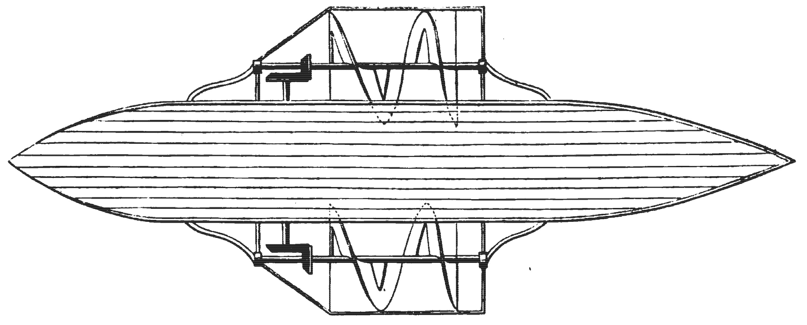
D. BUSHNELL. 1776.
In 1776, a submarine vessel was invented by D. Bushnell, an American, which was to be raised upwards, or sunk downwards, in the water, by a screw affixed to the top of the vessel; and moved backward or forward by another screw affixed to the bow, a rudder being placed at the stern to guide the vessel in any direction. This vessel was to carry a powder magazine, which could be screwed to the bottom of an enemy's ship; and a time- piece, in connexion with the magazine, was to fire the powder after the lapse of any time that was desired. This contrivance, which displays much ingenuity, was not found to be manageable in practice.
JOSEPH BRAMAH. 1785.
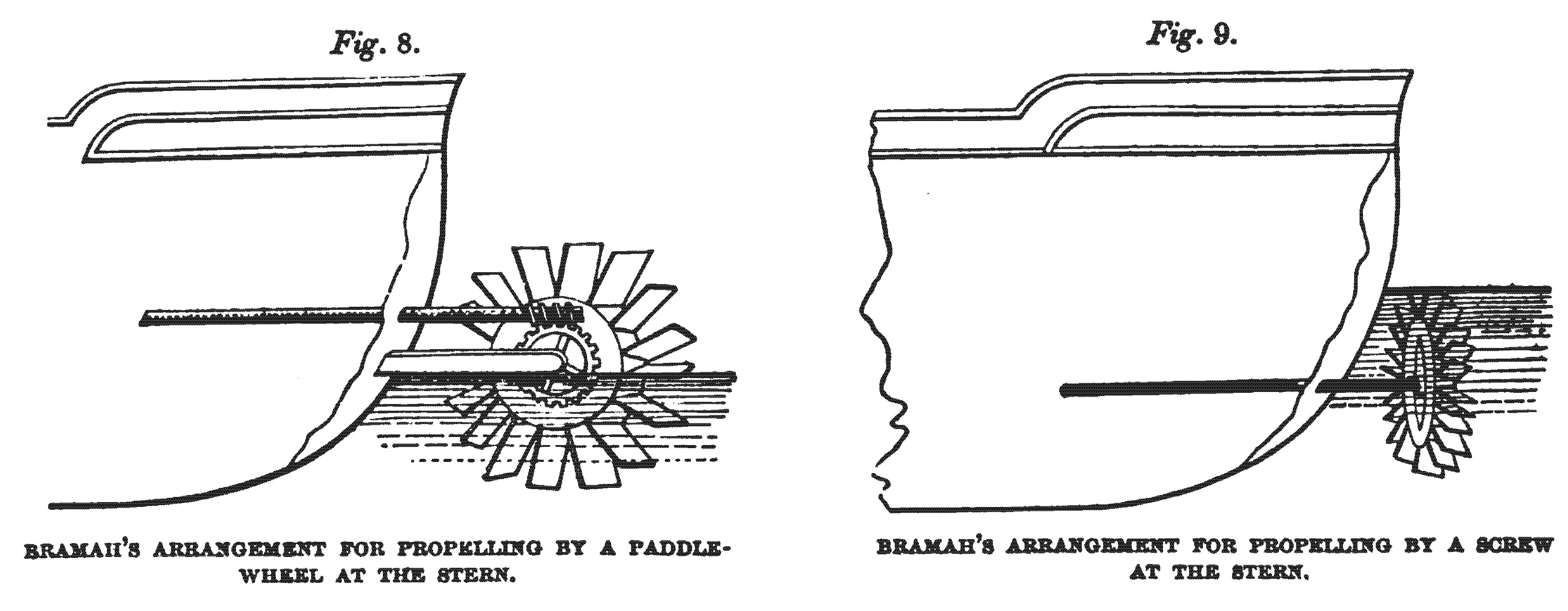
On the 9th May, 1785, Joseph Bramah, of Piccadilly, engine maker, enrolled a patent for various improvements in machinery, among which are described two new modes of propelling vessels through the water. The first of these contrivances consists in the application of a paddle-wheel to the stern of a vessel, which paddle-wheel is to be driven by a steam engine, - the rudder being placed in the bow, instead of the stern, to facilitate this adaptation. The second contrivance consists in the application to the stern of the vessel of “a wheel with inclined fans or wings, similar to the fly of a smoke-jack, or the vertical sails of a windmill. This wheel may be fixed on the spindle c (of the rotatory engine) alone (that is, without intermediate gearing), and may be wholly under water, where it would, by being turned round either way, cause the ship to be forced backwards or forwards, as the inclination of the fans or wings will act as oars with equal force both ways, and their power will be in proportion to the size and velocity of the wheel, allowing the fans to have a proper inclination.” Bramah explains, that where the engine shaft passes through the vessel, it is to be made tight by a stuffing-box, of which he gives a drawing ; but he does not give any drawing of his screw vanes, and fig. 9. is therefore constructed from the modification he describes as necessary to be made upon his drawing of the paddle-wheel, given in fig. 8., to represent the arrangement proper for the submerged propeller. The material parts of Bramah’s plan are anticipated. by the previous suggestions of Hulls, Bernouilli, and others ; but his general arrangement for fixing a screw at the stern, “in or about the place where the rudder is usually placed,” to be worked by a shaft proceeding direct from the engine, though vaguely described, is very judicious, and is such as would be perfectly successful if now carried into practice. There is no evidence to show that Bramah ever made, or tried, a propeller of this kind, and his rotatory engine, by which it was to be driven, turned out a failure.
WILLIAM LYTTLETON. 1794.
On the 11th November, 1794, William Lyttleton, of Goodman’s Fields, Middlesex, merchant, enrolled a patent for an instrument which he called the “Aquatic Propeller,” by which vessels were to be forced through the water. This propeller consisted of three helical feathers wound on a cylinder, as represented in figs. 10. and 11., and these cylinders were to be so fixed at the bow and stern, or at the sides, as to be immerged [sic] in the water, and to carry the vessel forward when put into revolution. Each cylinder, or screw, was to be turned by an endless rope, working in a sheave. An experiment was made with this screw by Lyttleton, in a boat in the Greenland Dock, and was witnessed by Colonel Beaufoy; but the effect was less than was expected, - the speed realised being only about two miles an hour. The invention was said to have been brought from China, from whence Lyttleton, who was a merchant, may have derived it.
EDWARD SHORTER. 1800.
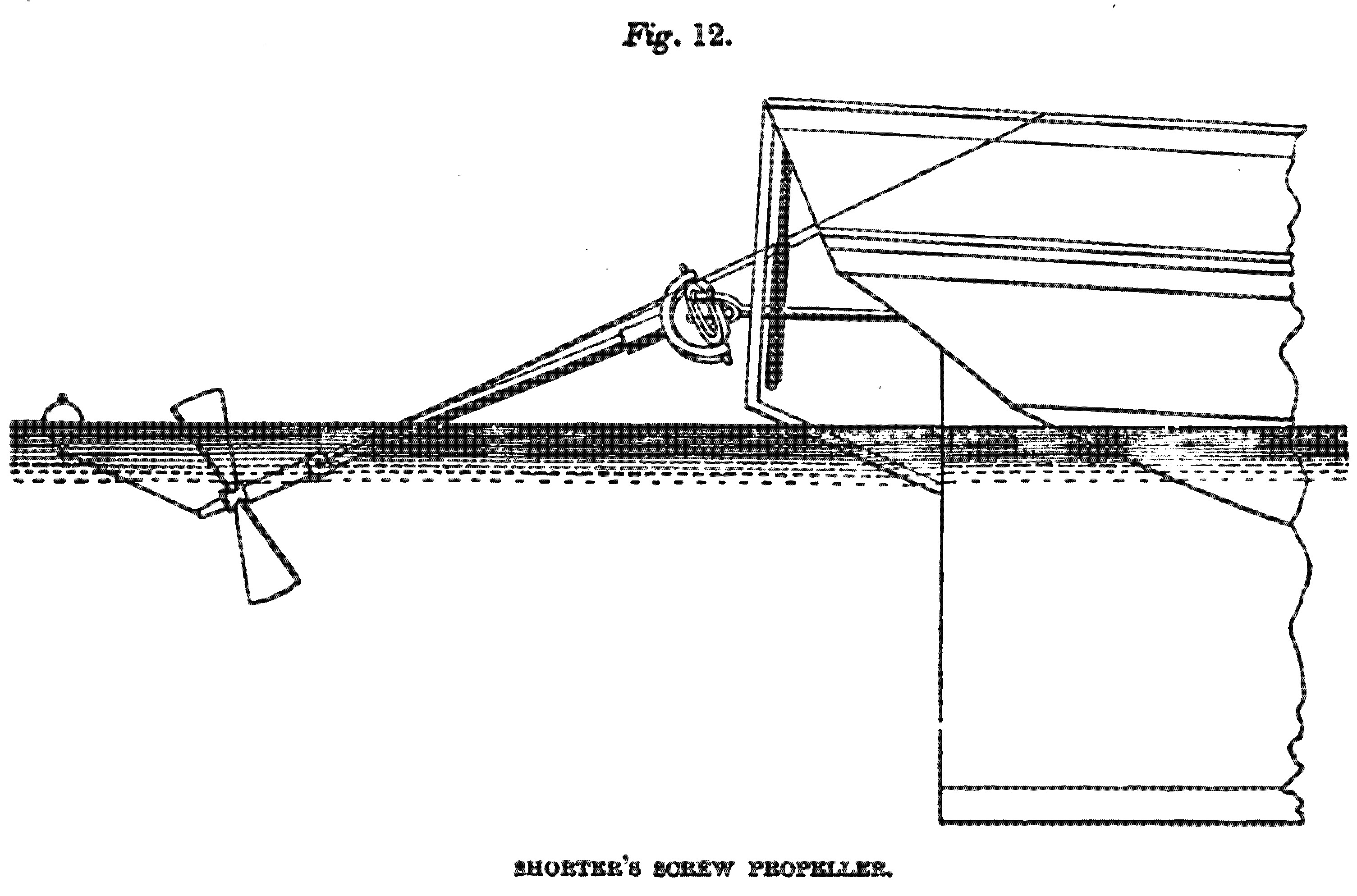
On the ist March, 1800, Edward Shorter, of St. Giles’-in-the-Fields, Middlesex, mechanic, enrolled a patent for propelling vessels by various expedients, among which, is one which he terms a “Perpetual Sculling Machine,” which consists of a screw of two or more blades, similar to the sails of a windmill, and which is to be immerged in the water, so that by being turned round by the capstan, or other appropriate machinery, it will propel the vessel. Shorter did not propose to give motion to his screw by a shaft passing through the vessel; but a spar was to proceed from any convenient part of the stern of the vessel obliquely downwards, until its end dipped into the water, and on the end of the spar, which was prevented from dipping too far by a buoy attached to it, the screw was to be fixed. The spar being put into revolution, carried the screw round with it, and a universal joint, on Hooke’s construction, was to be interposed at the head of the spar, so as to enable it to retain its oblique direction, though turned round by a horizontal shaft. The arrangement proposed by Shorter is shown in fig. 12.; and he states that, by pulling the guy ropes to the right or left of the spar, the ship may be steered by the influence of the screw. The principal object Shorter appears to have had in view, was to enable large vessels to be moved slowly in calms by the exertions of the crew; and he probably felt, that a shaft passing though the vessel below the water would have been considered objectionable, at that time, for the attainment of an occasional benefit. But he mentions also, that his propeller may be driven by a steam engine, and in that case it might have been kept in operation continually. Shorter applied one of his screws to the Doncaster transport, in 1802, and the result was considered very satisfactory; as, with eight men at the capstan, the vessel, though deeply laden, was propelled at the rate of 14 mile an hour. It appears probable that the propeller employed in this case had only a single arm. Mr. David Napier, who inspected Shorter’s models many years ago, found that he had screws of one, two, three, and four blades, and that he contemplated their application at the bow, in the dead wood, and at the sides of the vessel, as might appear preferable in each particular case.
M. DALLERY. 1803,
On the 23rd March, 1803, the citizen Dallery took a brevet of invention in France for an improved propeller. In his arrangement, a screw of two convolutions is applied to a vessel at the bow, and another similar screw is applied at the stern. The diameter of each screw swells larger in the middle of its length, and the length is equal to twice the pitch. There is no evidence to show that this project was ever practically tried, and its mechanical details are very crude and inartificial. The screws are turned by endless ropes, and the stern screw is affixed to the rudder, and moves therewith.
JOHN C. STEVENS. 1804.
In the year 1804, an attempt was made by John Cox Stevens, an American, to realise Bramah’s idea of propelling a vessel by means of a submerged propeller at the stern, formed in the manner of a windmill or smoke-jack, and driven by a rotatory engine. The rotatory engine was not found successful, and it was superseded by one of Watt’s engines, when the vessel attained a velocity of four miles an hour. Stevens began his experiments in steam navigation in 1791; and, during a part of the time, he was assisted by Livingstone, who was afterwards Fulton’s coadjutor in introducing vessels propelled by paddle-wheels. But his experiments upon the screw do not appear to have been considered satisfactory, as, after several trials, the project was abandoned. Part of this bad success may have arisen from, a deficiency of steam, as the boiler was a tubular one, of a new construction and small dimensions. For a short distance Stevens could make his boat go at a speed of seven or eight miles an hour, and the only material impediment to the maintenance of that speed would be a deficiency of steam.
HENRY JAMES. 1811.
On the 26th March, 1811, a patent was taken out by Henry James for improvements in the mode of navigating vessels. The chief object of these improvements was to enable vessels to be propelled upon canals, without inconveniently extending the width of the vessel; and the first arrangement specified is a paddle-wheel acting at the stern. But an alternative expedient is afterwards described as follows : — “ The oars, paddles, or propelling boards, instead of being made as before described, and revolving or turning in the direction of the lengthways of the boat or vessel, may be made like to the sails of a windmill or smoke-jack, pressing obliquely against the water, somewhat upon the principle of what watermen or sailors call sculling.”
RICHARD TREVITHICK. 1815.
On the 21st November, 1815, a patent was enrolled by Richard Trevithick, of Cambrone, Cornwall, engineer, for certain improvements in the high-pressure engine, and in its applications to useful purposes, in which a mode of propelling vessels by a worm, or screw, is comprehended. The screw is to consist of a number of leaves, placed obliquely around an axis, like the vanes of a windmill or smoke-jack, and is to revolve with great speed, having its axis in the same line as that in which the vessel moves. The obliquity of the thread of the screw, it is stated, admits of considerable variety, according to the velocity given to it, and speed required; but, as a general rule, the thread of the screw at its outer edge is to make with the axis an angle of 30 degrees. The worm or screw “ is in some cases to revolve in a fixed cylinder, in others to revolve together with the cylinder, similar to the screw of Archimedes; but generally to revolve in the water, without any cylinder surrounding it. This worm or screw may be made to revolve in the water at the head of the ship, boat, or other vessel, or at the stern; or one or more worms may revolve on each side of the vessel, as may most conveniently suit the peculiar navigation in which the ship, boat, or vessel is to be employed. In some cases, when the screw is to work at the head of a ship, it is to be made buoyant, and move on a universal joint at the end of an axle turning in the bow of the ship, in order that the screw may accommodate itself to the unevenness of the waves.” There is no expedient of propulsion in this patent, of any utility, which had not previously been suggested.
ROBERTSON BUCHANAN. 1816.
In 1816, there appeared “A Practical Treatise on Propelling Vessels by Steam, by Robertson Buchanan, Civil Engineer, Glasgow,” in which work the following passage occurs at page 68. "Experiments have been made on a kind of screw; but this, I believe, after a trial on a considerable scale in America, was rejected. Some mechanics, however, still think favourably of it, and suppose that if a screw of only one revolution were used, it would be better than where a longer thread is employed.” Subsequent experience has shown that this anticipation of the benefit of restricting the length of the screw is founded upon just views.
JOHN MILLINGTON. 1816.
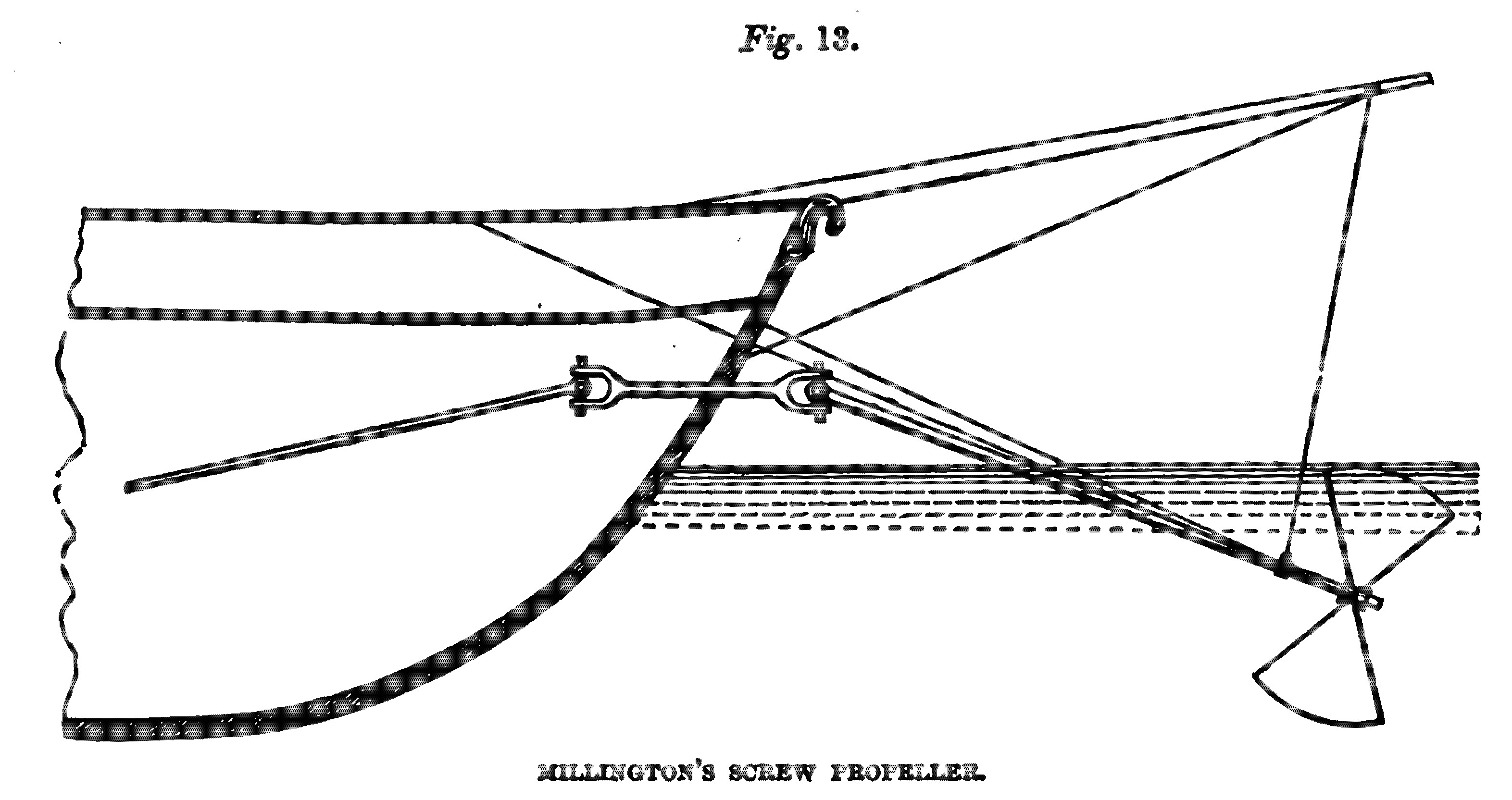
On the 31st July, 1816, a patent was enrolled by John Millington, of Hammersmith, civil engineer, for an improved method of propelling vessels by the use of a screw, or by forcing air out at the stern, or by the two methods combined, where great speed is required. The arms of the screw are to resemble the vanes or sails of a windmill, and the patentee states, that he has found “that two vanes, each extending to about a quadrant of a circle, produce a greater effect than any other number.” These vanes are to be made “to shift on their pivots or points of attachment, so as to alter the angle which they make with the plane of their motion from 45 degrees to any greater or lesser angle, according to the speed with which they are moved, or the velocity wanted to be communicated to the vessel. The use of moveable vanes had previously been introduced by Hooke in his screw vanes for measuring the velocity of the wind; and the shaft which,.in Millington’s arrangement, carries the screw, is to have a Hooke’s, or universal joint, at the point where it emerges from the vessel, to the end that it may be lowered to any depth in the water that may be required, or raised out of the water if necessary, — its immersion being regulated by a rope hanging from the bowsprit, or from a projecting beam in the situation of the bowsprit, the end of which rope is attached to a loose collar on the shaft. Guide-ropes are also applied to each side of the shaft, in order that the screw may be pulled sideways to the right or left, and the vessel may be steered, or assisted in the steerage, thereby. The upper end of the shaft, carrying the screw, is to rise just above the water line; and, at that level, a short shaft is to pass through the ship, the hole being made water-tight by means of a stuffing-box encircling a short horizontal shaft, at the inner end of which, as well as the outer, there is to be a universal joint, which will prevent the machinery from being incommoded by any working of the ship. This arrangement is shown in fig.13. Millington says, that the screw may either be worked by horses, or by a steam engine, and that he proposes to apply it “either at the head or stern of the vessel, or at both of them at the same time.”CAPTAIN DELISLE. 1823.
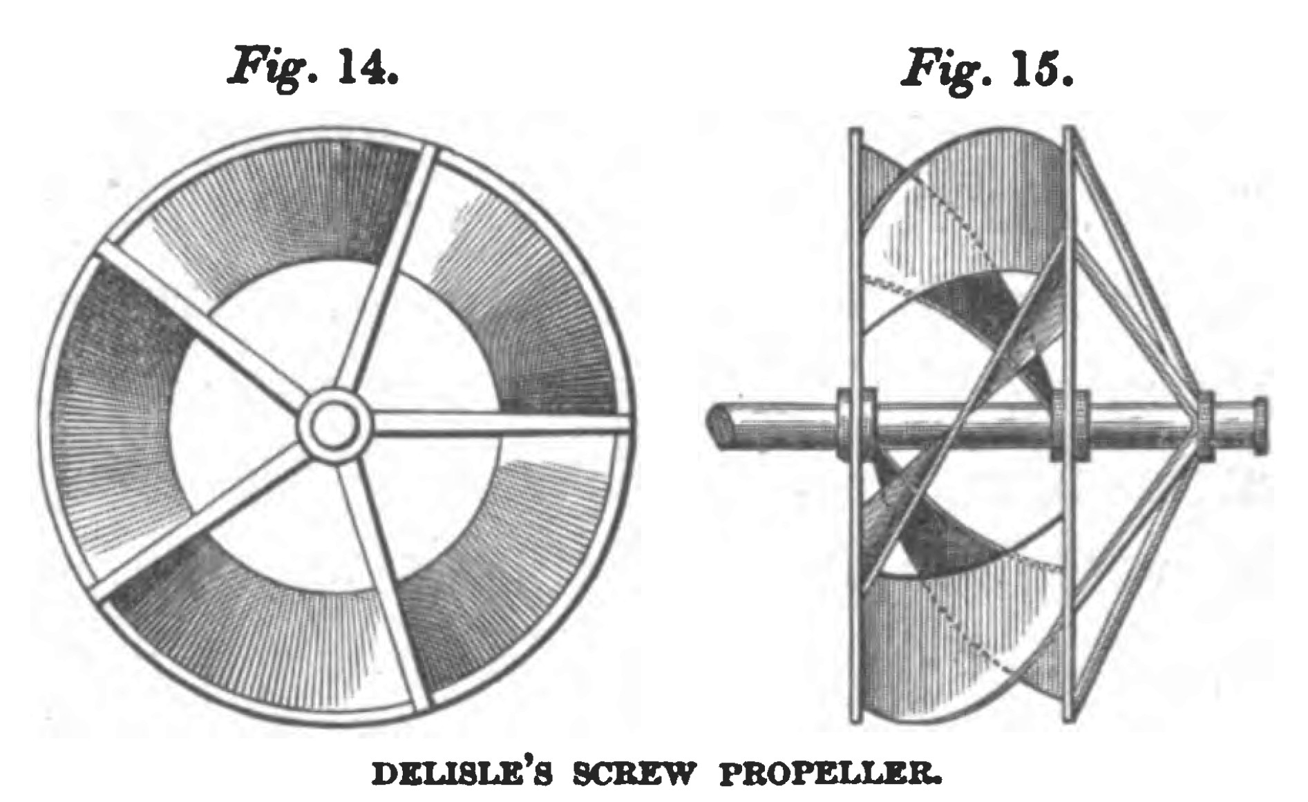
In the month of June, 1823, Captain Delisle, of the French Engineers, presented to the Minister of Marine a memoir on a mode of propelling vessels by means of a submerged screw, resembling some of those previously proposed; but the central part of the screw was cut away, in the manner shown in figs. 14. and 15., and the helical surface was disposed around the outside of the circle, somewhat in the manner adopted in Lyttleton’s arrangement; but five threads were employed instead of three, and the length of the screw was only equal to a fifth of the pitch. This arrangement of the helical surface, in the case of windmills, had previously been suggested by Ferguson, in his lectures on Natural Philosophy. He says, “ As the ends of the sails nearest the axis cannot move with the same velocity that the tips or farthest ends do, although the wind acts equally strong upon them, perhaps a better position than that of stretching them along the arms, directly from the centre of motion, might be to have them set perpendicularly across the further ends of. the arms, and there adjusted, lengthways, to the proper angle. For, in that case, both ends of the sails would move with the same velocity, and, being farther from the centre of motion, they would have so much the more power; and then there would be no occasion for having them so large as they are generally made, which would render them lighter, and, consequently, there would be so much the less friction on the thick neck of the axle, where it turns in the wall.” [* Ferguson’s Lectures on Select Subjects, p. 84. London, 1776.]
Delisle’s memoir, addressed to the Minister of Marine, led to no result, and was completely forgotten; but, lately, it has been raked up by the French Government, to furnish a pretext for an evasion of Ericsson’s patent in France, where it has been largely adopted. If the French Government had acted upon Delisle’s representations, — if they had built vessels, instituted experiments, and taken the other steps necessary to perfect the system of screw propulsion, and to bring it into practical use, there might be, at least, a plausibility in their pretensions. But on what principle of equity can they expect to reap the reward of successes, in the realisation of which they had no part whatever, and which they, manifestly, deemed of hopeless attainment, since they refused to sanction any expenditure to enable them to be achieved? Before the time of Delisle, propellers shaped like windmill sails had frequently been proposed, and it had been explained by Emerson and others that, in windmill sails, “the tangents of the angles ought to be nearly as the distances from the centre”, or, in other words, that the sails of a windmill should have such a twist as nearly to constitute them portions of a screw, — though, indeed, windmill sails have been made with such a twist from a remote antiquity. The use of helical surfaces for propelling, therefore, was not new in 1823, nor was the idea new of disposing these surfaces circumferentially ; but the practical adaptation of the screw as an effectual propeller had not at that time been accomplished, and this adaptation and introduction of the screw Delisle did nothing to promote.
M. MARESTIER. 1824.
In 1824, a memoir, by M. Marestier, on the steam vessels of America, was published by the direction of the French Government, and arrangements for the propulsion of a vessel by a screw of several convolutions, are there exhibited. In one of these arrangements the bottom of the vessel is raised upwards, in an arch, from stem to stern, and in this arch a screw, or helix, nearly of the length of the vessel, is placed. In another arrangement, two helical feathers are placed in the central channel of a twin boat, and these helical feathers or screws are turned in opposite directions by means of gearing.
M. BOURDON. 1824.
In 1824, a brevet of invention was taken out, in France, by M. Bourdon, an engineer in that country, for propelling vessels by means of a screw, and this screw was to be made with an expanding or increasing pitch. A company was formed to carry out M. Bourdon’s invention, and it was introduced into a steam vessel on the Rhone, but was subsequently abandoned.
JACOB PERKINS. 1825.
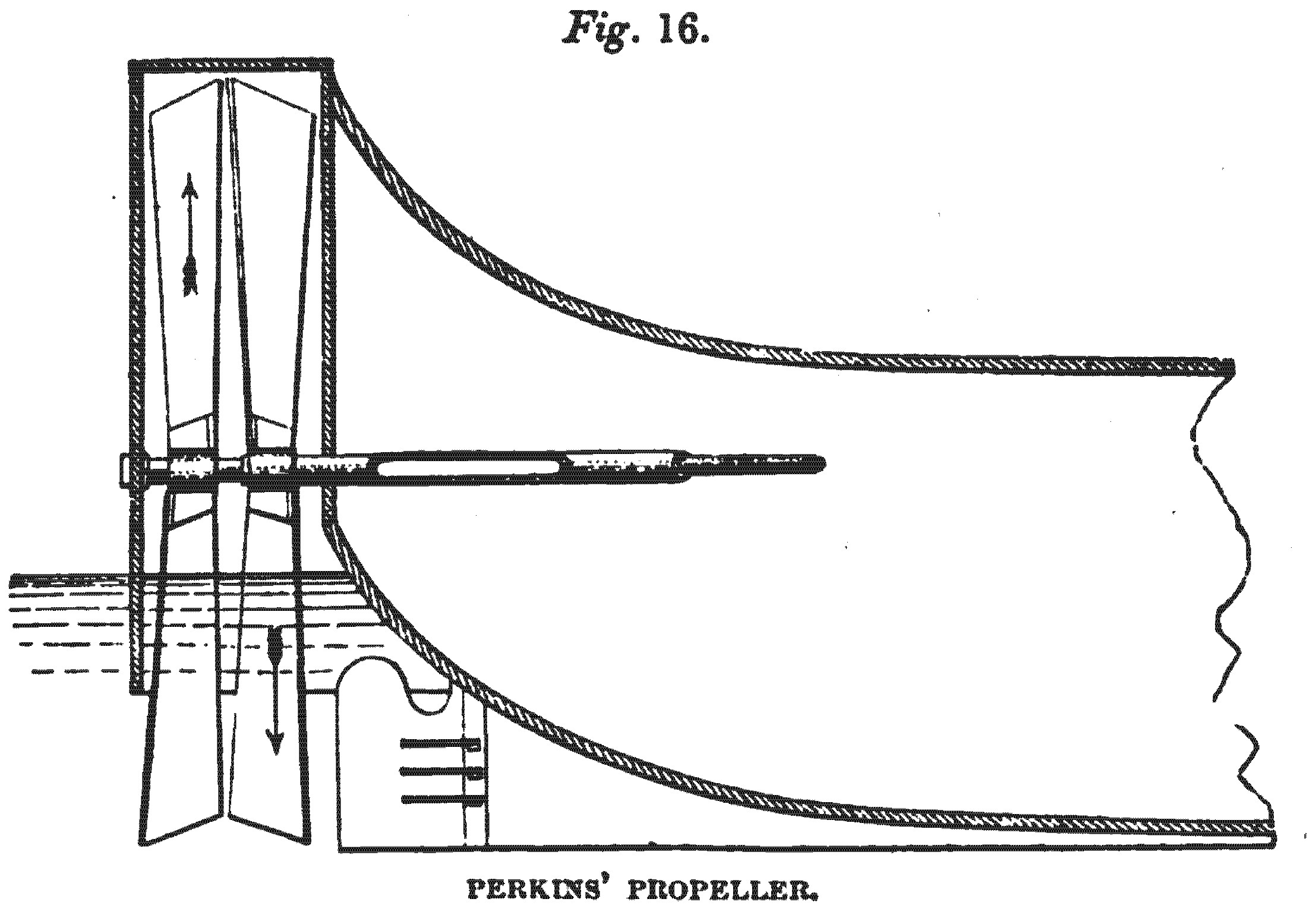
On the 9th February, 1825, Jacob Perkins, of London, engineer, enrolled a patent for an improved method of propelling vessels, the general arrangement of which is shown in fig. 16. At the stern of the vessel is placed two blades, or arms, resembling the vanes of a windmill, and these double blades are placed one before the other, and are only partially immersed in the water. Each blade has an angle of 45 degrees with the shaft at the centre, and 224 degrees at the circumference, and the obliquities run in opposite directions, — the one in the manner of a right-hand screw, and the other in the manner of a left-hand screw. The shaft of the pair of blades next the vessel is hollow, and the shaft of the other pair passes through it; and each pair of blades is turned in opposite directions by appropriate mechanism. The object of this arrangement is to keep the vessel steady, and to neutralize any propensity which one pair of blades, or one screw, might have to turn the vessel round. The blades are hung in a frame, which may be raised or lowered to suit the varying immersions of the ship. On the 2nd July, 1829, Perkins obtained another patent, for improvements on the foregoing; in which he placed one propeller-wheel over each side of the vessel, the shafts running obliquely forward, and meeting at an angle of 45 degrees in the middle of the deck. Some experiments upon a vessel, propelled upon this plan, are recorded in the Journal of the Franklin Institute, and the result appears to have been satisfactory.
SAMUEL BROWN. 1825.
In the year 1825, a company, which had been formed for carrying into operation Mr. Samuel Brown’s project of a gas vacuum engine, offered a reward of 100 guineas for the best suggestion for propelling vessels without’ paddle-wheels, and the reward was gained by Mr. Samuel Brown, who proposed to accomplish the desired object by a screw, placed in the bow of the vessel. The company having determined to carry out this idea, a vessel was built and fitted with a screw; and, with this vessel, a speed of six or seven miles an hour is said to have been attained. The project of the application of a screw, however, having been subsidiary to the introduction of the gas vacuum engine, and the gas vacuum engine having failed, the screw participated in the discredit of the miscarriage: the company was broken up, and the scheme was abandoned.
THOMAS TREDGOLD. 1827.
In the first edition of Tredgold’s “Treatise on the Steam Engine,” published in 1827, some remarks are made upon the screw as a propeller for steam vessels; and it is related that a screw, working in a cylinder, had been proposed by Mr. Scott, of Ormiston, and that two screws, working in opposite directions, had been tried by Mr. Whytock, as mentioned in Brewster’s “Philosophical Journal,” vol. ii. p. 39. Tredgold goes into a mathematical investigation to show the impropriety of using screws of many convolutions, — a doctrine previously suggested by Buchanan; and he also indicates, as Emerson before had done, the benefit of making screws with an expanding or increasing pitch. He says, “A second revolution, at the same angle, could have very little action, because the water would have acquired all the velocity the spiral could communicate. If it be continued, therefore, it should be made with a decreasing angle.”
CHARLES CUMMEROW. 1829.
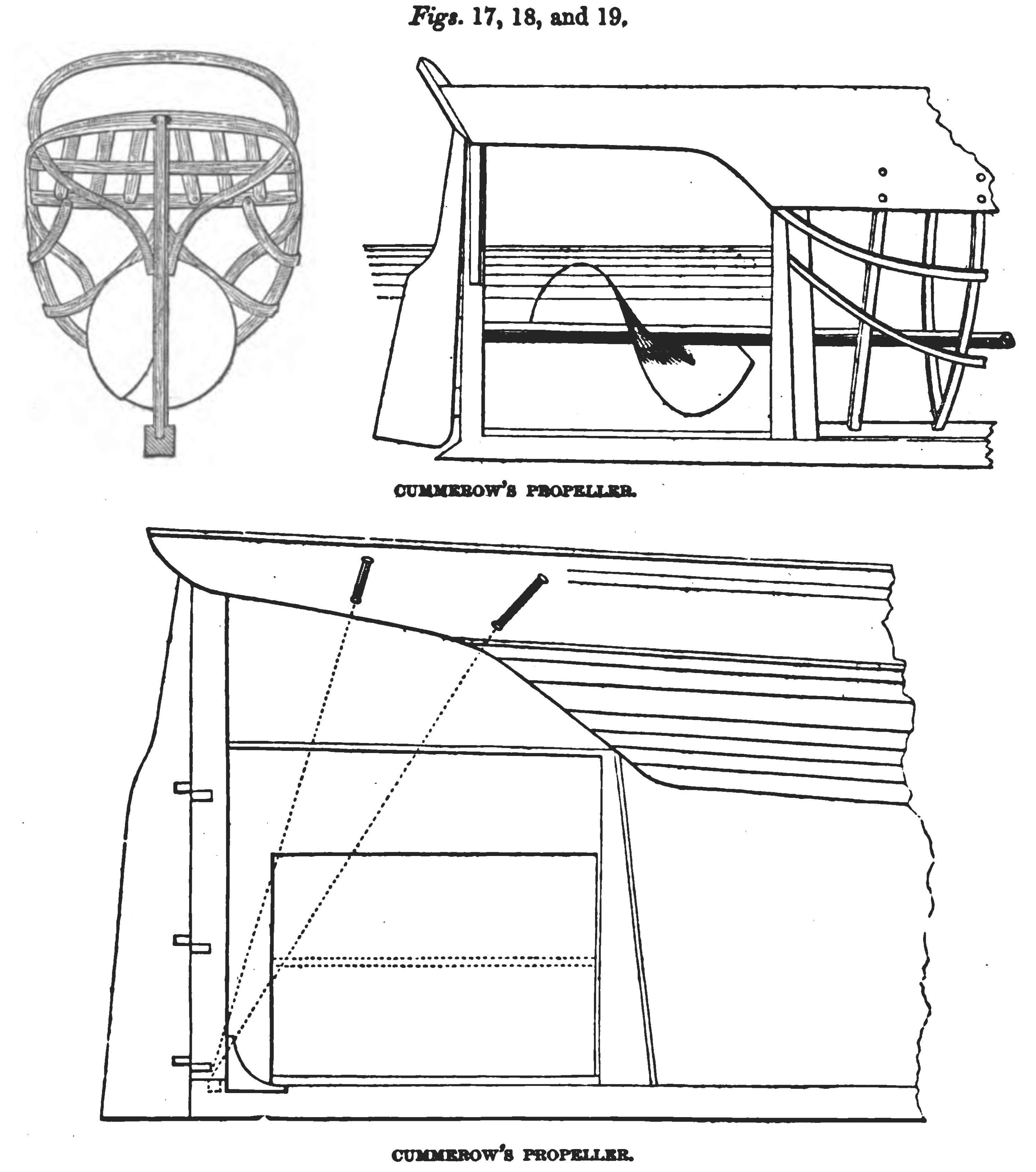
On the 10th June, 1829, a patent was enrolled by Charles Cummerow, of Lawrence Pountney Lane, London, merchant, for improvements in propelling, communicated by a foreigner residing abroad. These improvements consist of a variety of arrangements for applying a screw in the propulsion of vessels, and the screw is to have a single thread of one circumvolution, the proportion of the pitch to the diameter being as one to two. In the case of sea-going vessels, the screw is to be fixed at the stern, in the manner suggested by Bramah and other preceding inventors; but the rudder, instead of being fixed to the bow or set before the screw, is to be fixed to a false stern-post abaft the screw, which false stern-post is to be connected to the ship by appropriate frame-work. The propeller shaft, where it passes through the ship, is to be encircled by a stuffing-box, which is to be kept tight by means of tallow. The specification of this patent is very illiterate and obscure, having been apparently drawn up by a foreigner imperfectly acquainted with English; and it 1s full of mis-spelled words and unintelligible phrases, which sometimes make it difficult to determine the meaning. The general arrangement, however, is shown in jigs. 17, 18, and 19., and the only novelty is in placing the screw in a framework built on to the ship, to the end of which framework a rudder is affixed.
WILLIAM CHURCH. 1829.
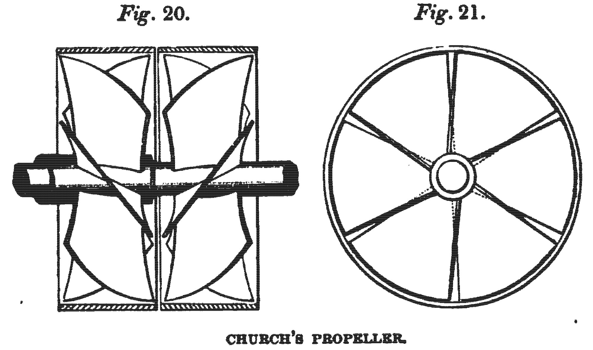
On the 15th October, 1829, a patent was taken out by William Church, of Haywood House, near Birmingham, for improvements inf the mode of propelling vessels. These improvements consist in the use of two wheels, figs. 20. and 21., revolving in opposite directions, as previously proposed by Perkins; but instead of two blades being attached to each shaft, a number of bent paddles, placed upon cylindrical rings, were to be employed, in the manner proposed by Delisle. These bent paddles were to be set in opposite directions, and might be placed within a fixed cylinder. Church does not say whether his propeller was to be placed at the bow or stern, or whether it was to be totally or only partially immerged, or whether it was to be a helix or any other curve; and the different views given of the propeller do not correspond.
M. SALICHON, 1831.
On the 21st June, 1831, a brevet of invention was taken out in France, by M. Salichon, an engineer, for “a new system of navigation, in which one may make use of every kind of screw.” He says, the screw which he proposes to employ is the common one, “invented by Architas 400 years before our era;” and he describes the mode of applying it in the bow of the vessel, where it is to be driven by a shaft passing through a stuffing-box, in the manner previously adopted by Sir Samuel Brown; or it may be applied in the stern, in the manner suggested by Bramah and other inventors.
BENNET WOODCROFT. 1832.
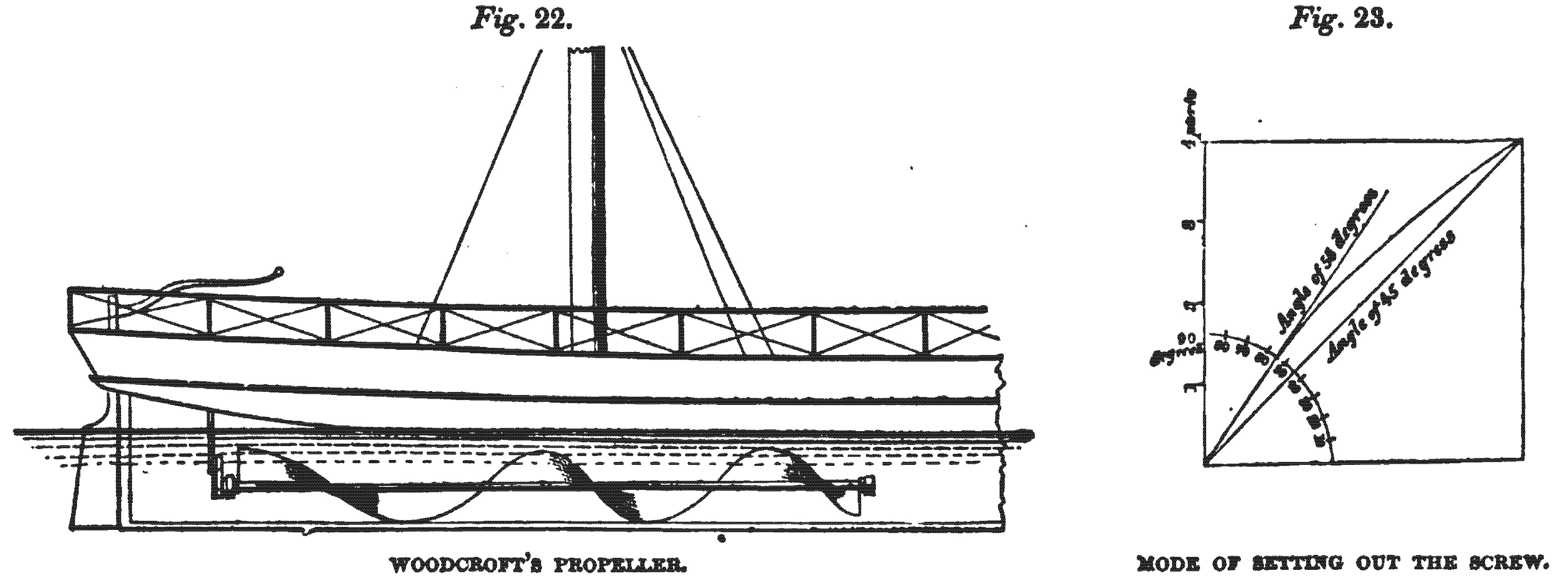
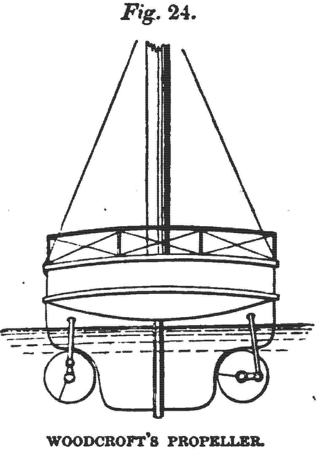
On the 20th September, 1832, a patent was enrolled by Bennet Woodcroft, of Manchester, printer, for “improvements in the construction and adaptation of a revolving spiral paddle, for propelling boats and other vessels on water.” In the drawings accompanying this specification, of which a specimen is given in figs. 22, 23, and 24., various screws, of several convolutions, are represented as applied to the stern and sides of a ship; but the main feature of the arrangement is, that the spiral feather shall be coiled round the shaft, or supporting cylinder, “in such form, that the angle of inclination which the worm makes with the axis of the cylinder continually decreases, and the pitch or distance between the coils or revolutious of the spiral continually increases, throughout the whole length of the shaft or cylinder.” This is the principle of the expanding or varying pitch, — enunciated long before by Emerson, introduced into practice in France, by Bourdon, in 1824, and recommended for adoption by Tredgold, in England, in 1827; so that this principle was not a novelty at the time Woodcroft’s patent was taken out.
WILLIAM HALE. 1836.
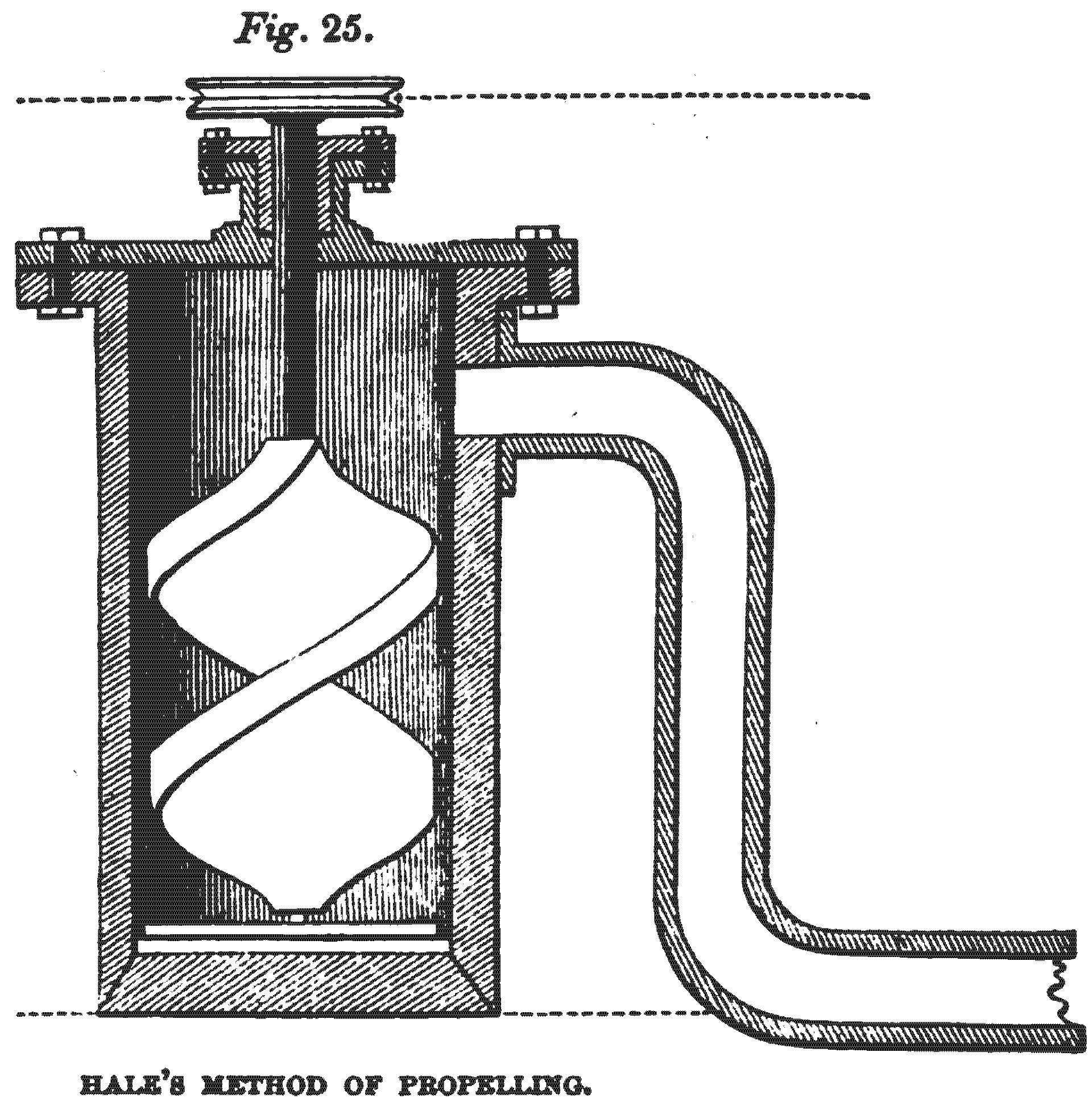
On the 22nd March, 1836, as also in 1827 and 1830, patents were taken out by William Hale, of Greenwich, civil engineer, for a method of propelling vessels by forcing water out at the stern, and, in some of the arrangements, a screw acting within the vessel was employed to force out the water; but, as this screw only acted in the manner of a pump, the plan can scarcely be comprehended among expedients for screw propelling. This method of propelling had been proposed nearly two centuries before by Toogood, and had been tried by Rumsey, an American, in 1788, and subsequently by Linaker, Lilley and Frazer, and others, but without success; owing, probably, to the dimensions of the discharging orifice being too small, which caused a waste of power by slip. One of the arrangements proposed by Hale, is shown in fig. 25.
FRANCIS PETTIT SMITH. 1836.
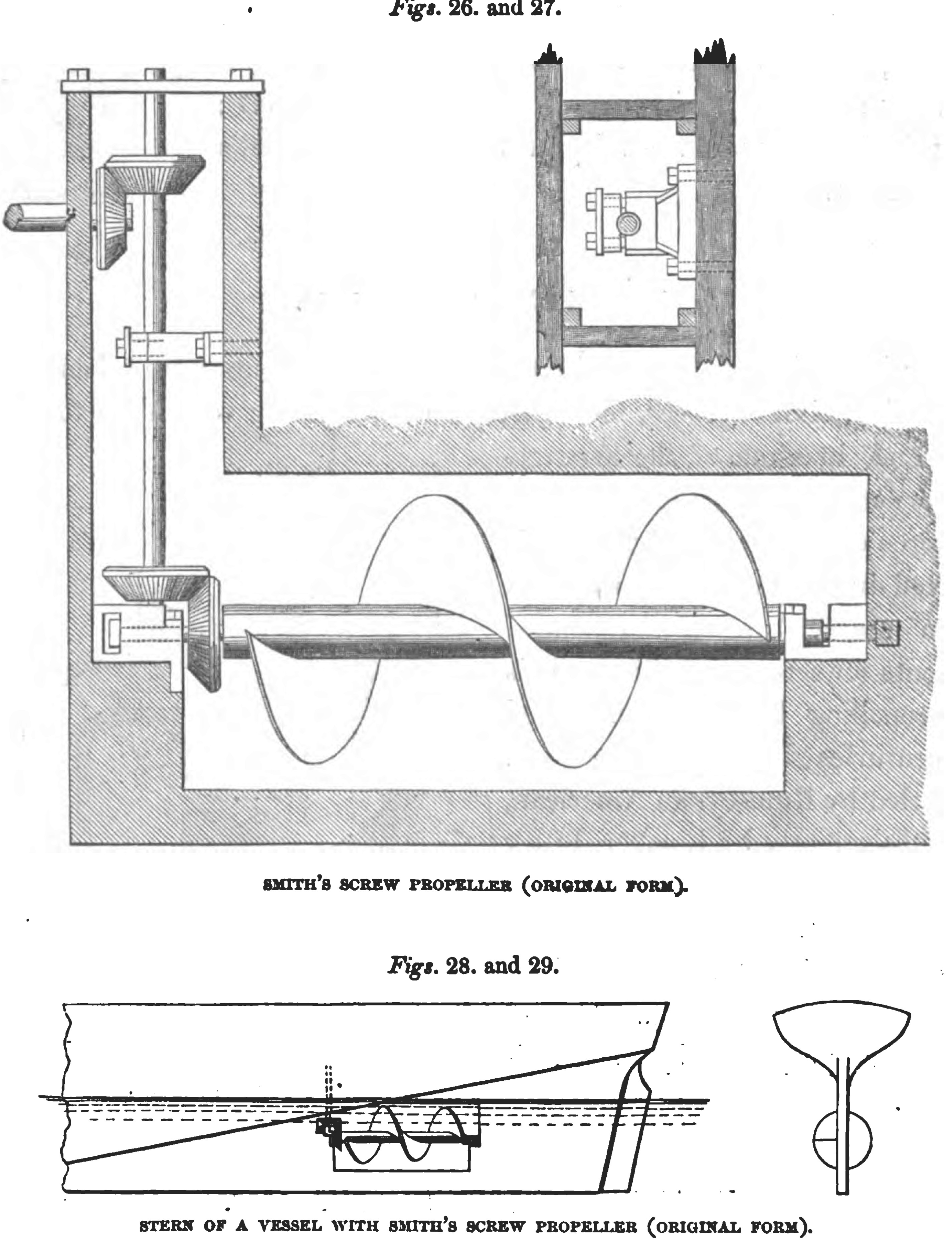
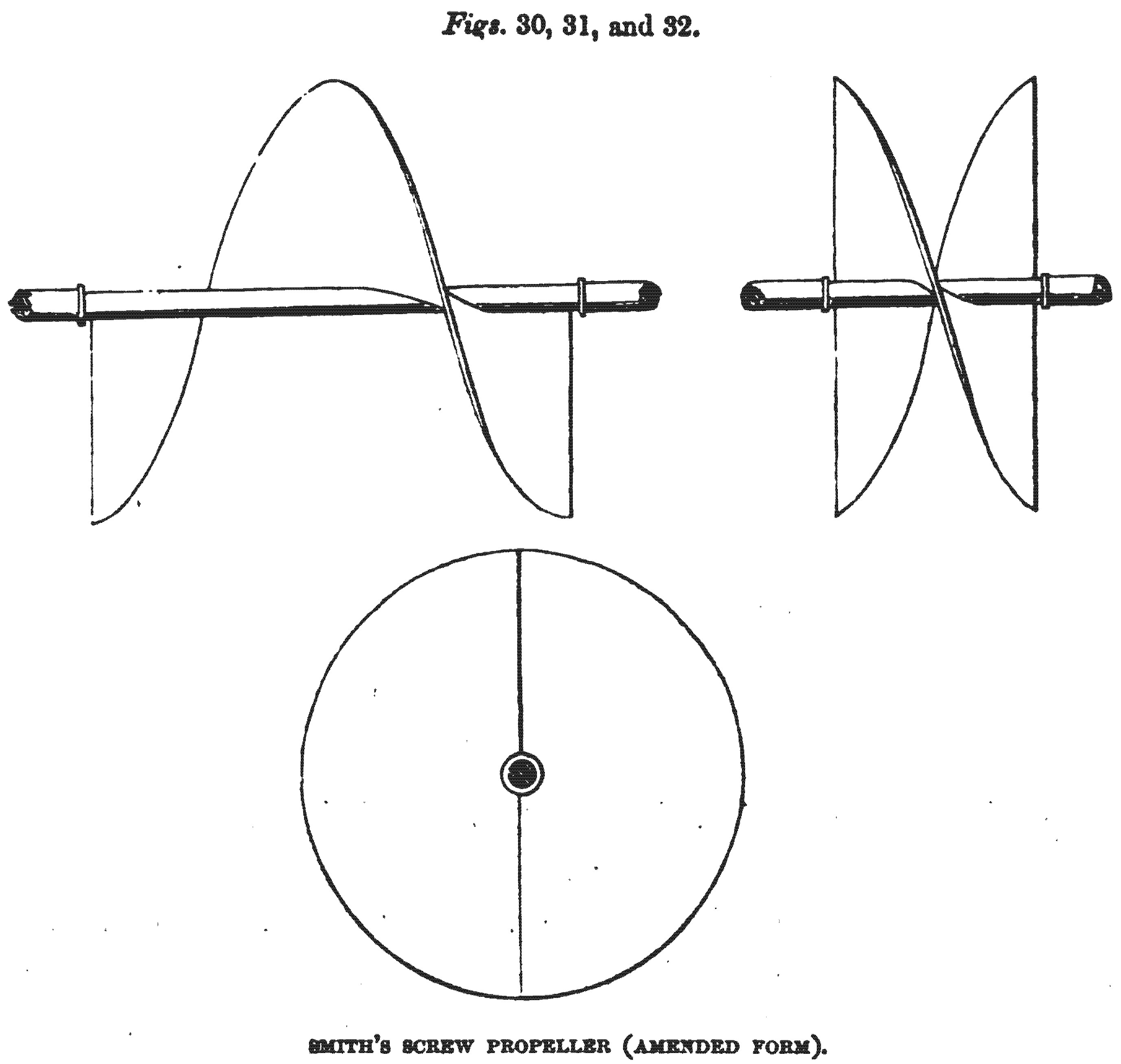
On the 31st May, 1836, a patent was taken out by Francis Pettit Smith, of Hendon, in the county of Middlesex, farmer, for an improved propeller for steam and other vessels, which improved propeller is stated “to consist in a sort of screw or worm, made to revolve rapidly under water, in a recess or open space formed in that part of the after part of the vessel commonly called the dead rising or dead wood of the run.” In the drawings accompanying the specification, a screw of a single thread, and of more than one convolution, is represented; but it is stated that a screw of not more than one thread may be employed, and that the threads may have any required angle with the shaft of the propeller. The patentee claims the use of screws, “whether arranged singly, or in an open space in the dead wood, as here shown (figs. 26, 27, 28, and 29.), or in duplicate, with one on each side of the dead wood, or otherwise placed more forward or more aft, or more or less deep in the water;” but, on the 30th April, 1839, he entered a disclaimer, limiting his claim to the use of a single-threaded screw of one convolution, or a double-threaded screw of half a convolution (figs. 30, 31, and 32.), introduced into the centre of the dead wood. Smith’s double-threaded screw is the form of screw most commonly adopted in this country ; but, instead of half a convolution, one-sixth of a convolution is found to give the best result, though the length to give a maximum performance will, in some measure, depend on the kind of vessel to which the screw is applied.
JOHN ERICSSON. 1836.
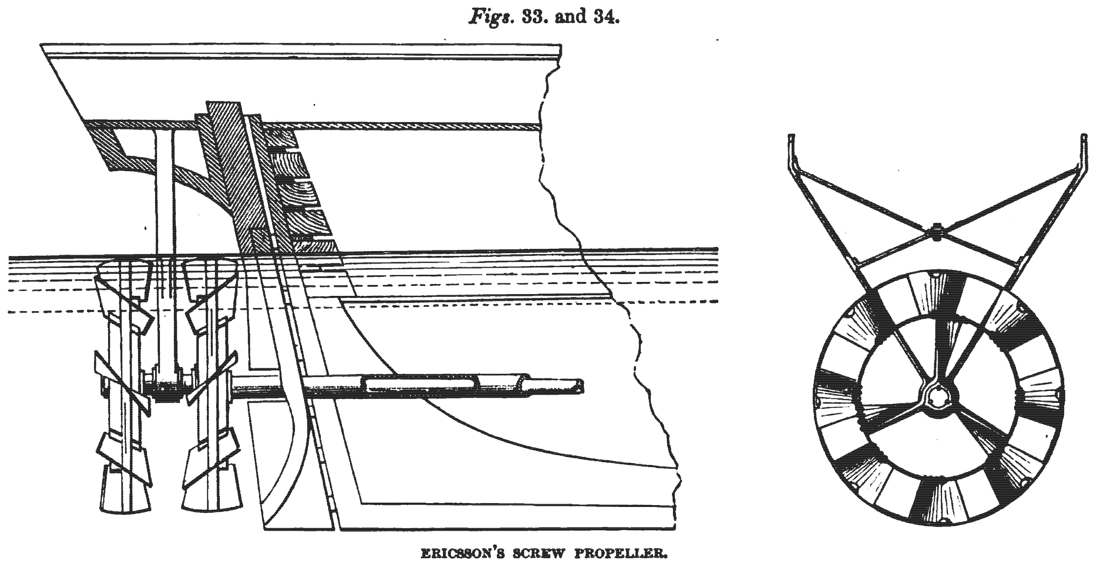
On the 13th July, 1836, a patent was taken out by John Ericsson, of London, engineer, for an improved propeller applicable to steam navigation, which propeller is described as consisting of “two thin broad hoops, or short cylinders, made to revolve in contrary directions round a common centre, each cylinder or hoop moving with a different velocity from the other; such hoops or cylinders being also situated entirely under the water at the stern of a boat, and furnished each with a series of short spiral planes or plates, — the plates of each series standing at an angle the exact converse of the angle given to those of the other series, and kept revolving by the power of a steam engine.” The general arrangement of the propeller prescribed by Ericsson, is shown in figs. 33. and 34., and the plates are to be “coiled round the cylinder spirally, like the thread of a screw,” — a large figure of a screw being appended to the specification, to show that it is a segment of a screw of several threads, that is intended to be employed. Ericsson’s propeller has been found very successful in practice, and it is the kind of screw most used in France and America. The cylinders to which the blades are attached, are not otherwise important, than as serving for the attachment of the blades without filling up the centre of the screw with a multitude of arms; but the outer cylinder or ring may be useful, in some cases, in preventing the entanglement of ropes or ice by the propeller. In some cases, Ericsson makes use of two screws, one behind the other, as shown in the figure. In other cases, he makes use of two screws side by side, one being placed in each quarter; but, in the generality of cases, he uses a single screw of a number of threads placed before the rudder in the stern. In some of its general features, Ericsson’s plan resembles the previous arrangements of Perkins and Church ; but Ericsson’s propeller is completely submerged, and is so complete in its mechanical details, that, when tried, it was at once found to be efficient. The purpose of causing the hinder screw to revolve at a swifter velocity than the other, is to enable it to act upon the water which has been already set in motion, and thereby secure the advantages of an increasing pitch. But this object is not important, since an equally augmented reaction may be obtained by somewhat increasing the diameter of the first screw.
JAMES LOWE. 1838.
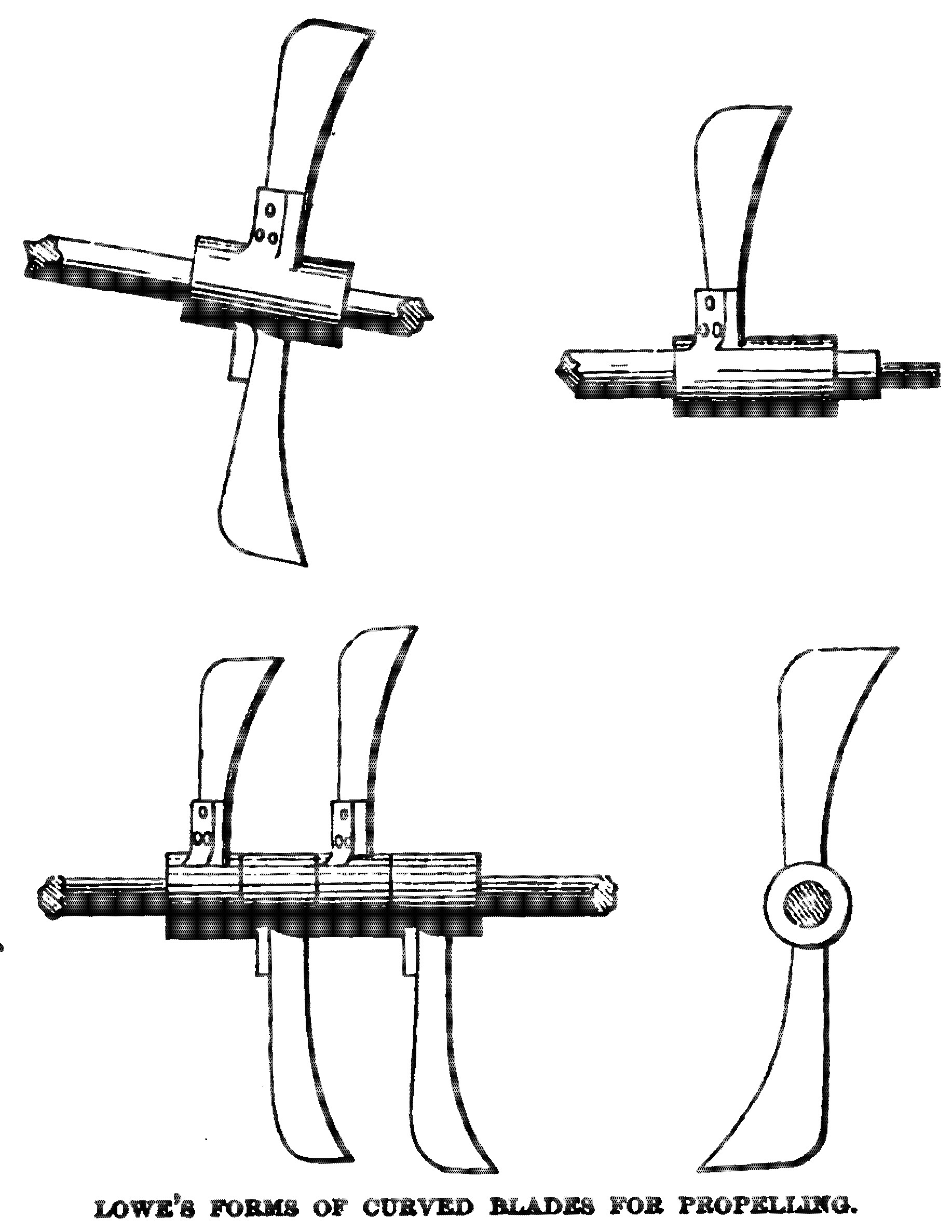
On the 24th September, 1838, a patent was enrolled by James Lowe, of London, mechanic, for improvements in propelling vessels, of which improvements only one is described, and that consists in the use of one or more curved blades, set on a revolving shaft below the water line, those curved blades being of such a form, that, if continued, they would produce a screw. The form and arrangement of these curved blades are shown in Figs. 35, 36, 37, and 38., — the arrangement with four blades being alleged to be the best. The patentee states that he is aware segments of a screw had been previously patented by Edward Shorter, and that he does not claim, therefore, the application of curved blades generally; but that, inasmuch as Shorter’s propellers were carried by outriggers over the bow of the vessel, and his are carried by a shaft lying below the water line, which pierces through the vessel, he claims the use of one or more curved blades, on shafts or axes, below the water line. It is clear, however, that this claim can in nowise be substantiated, since, in the arrangements of Bramah, Stevens, Brown, and Ericsson — all of previous date — curved blades, forming but a small part of a complete convolution of a screw, were employed, in conjunction with shafts or axes, below the water line; and there was no novelty, therefore, in such a combination at the time this patent was taken out.
JOSEPH J. O. TAYLOR. 1838.
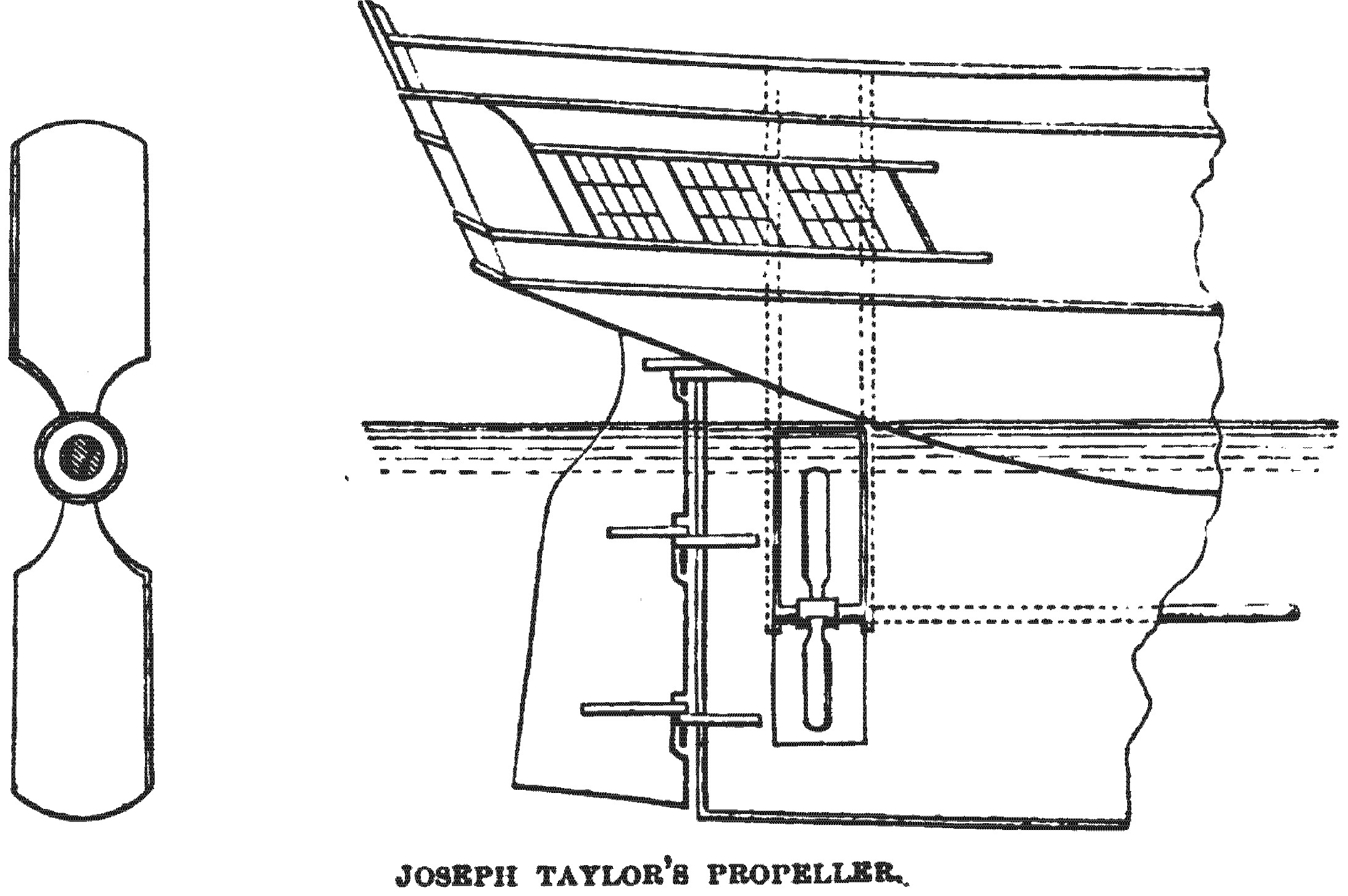
On the Ist May, 1838, a patent was taken out by Joseph Jepson Oddy Taylor, of London, machinist, for an improved mode of propelling ships and other vessels. Mr. Taylor’s invention, which is represented in jigs. 39. and 40., is described as consisting of two blades, set on an axis, placed in the run or dead wood, and acting in the manner of a screw; but the blades are flat instead of helical, being like the blades of an oar, instead of having a curve, or twist, like the screw.
A method is also claimed of shipping and unshipping the propeller by the aid of a sliding-frame, or sash, guided by vertical grooves cut in the true and false stern posts, and in which frame the propeller is placed. By drawing the driving shaft inward through the stuffing-box, the frame and screw can be drawn out of the water, and either rested on deck or placed in a boat alongside.
FREDERICK E. FRAISINET. 1838.
On the 26th July, 1838, a patent was taken out by Frederick Edouard Fraisinet, of Westminster, for improvements in the machinery for propelling vessels by steam. This patent prescribes the use of a revolving propeller on each side of the vessel, formed in the manner of a screw, — an arrangement contemplated by most of the preceding inventors; but these screws are to have the central portions cut away, as recommended by Fergusson, Delisle, and Ericsson, and are to be formed with an increasing pitch, as previously suggested by Emerson, Bourdon, Tredgold, and Woodcroft. The propellers are to be put into revolution by level gearing, and the general arrangement, in which there is nothing very novel or advantageous, is represented in Fig. 41.
CAPTAIN SMITH, R.N. 1838.
On the 13th November, 1838, a patent was taken out by Captain George Smith, of the Royal Navy, for improvements in vessels to be propelled by steam, or other power, and in the construction and arrangement of the machinery for propelling. One of the improvements Captain Smith describes is the paddle-box boat, which some years since obtained considerable introduction; but the main improvement is a method of
[ to be continued at image 35 ... ]
Footnotes:
[ Back ] Footnote 1: Ferguson, in his “Lectures on Select Subjects,” delivered about a century ago, explains that the vanes of windmills must have a twist, “causing all the ribs of the vane to lie in different planes;” and this twist, he explains, should be regulated “according to the different velocities from the axis to the extremity of the vane,” so that the same angular velocity would be generated, upon whatever part of the vane the wind was made to impinge. The same explanation, of the considerations regulating the twist of the vanes, is given by previous mathematical writers, and vanes made upon this principle would constitute portions of a true screw. But in the practical rules given by Smeaton and other engineers for setting out windmill vanes, the vanes do not form portions of a true screw. If the arm of a screw of 35 ft. pitch, be divided in the direction of its length into six equal parts, and the pitch be taken near the centre, at the circumference, and at the four intermediate positions, it will be found to be 35 ft. at each point; but if the arm of a windmill made according to Smeaton’s rules be similarly divided, the pitch at the circumference will be 23 1/2 ft., at the next point 35 ft. at the next point 35 ft., at the next point 30 ft. 9in., at the next point 21 1/2 ft., and at the point nearest to the centre 10 ft. The purpose of this deviation from the form of a true screw, in setting out the vanes, is to accomplish certain practical objects, of which one is, that in consequence of the elasticity of the arm, it would be warped out of the form of a true screw by the pressure of the wind, if made of the form of a true screw at first; and it is therefore made of such a shape, that the form approaches more nearly to that of a true screw when the wind is passing through the vanes. Near the centre of the arms the wind imparts but little rotative force, so that a deviation from the true screw form there is not of importance, and the pitch is reduced very much near the centre, to keep the vanes clear of the tower in which the windmill revolves, to adjust them to the lower velocity of the wind due to the obstruction presented by the tower, and to obviate the necessity of any great overhang of the windmill shaft.