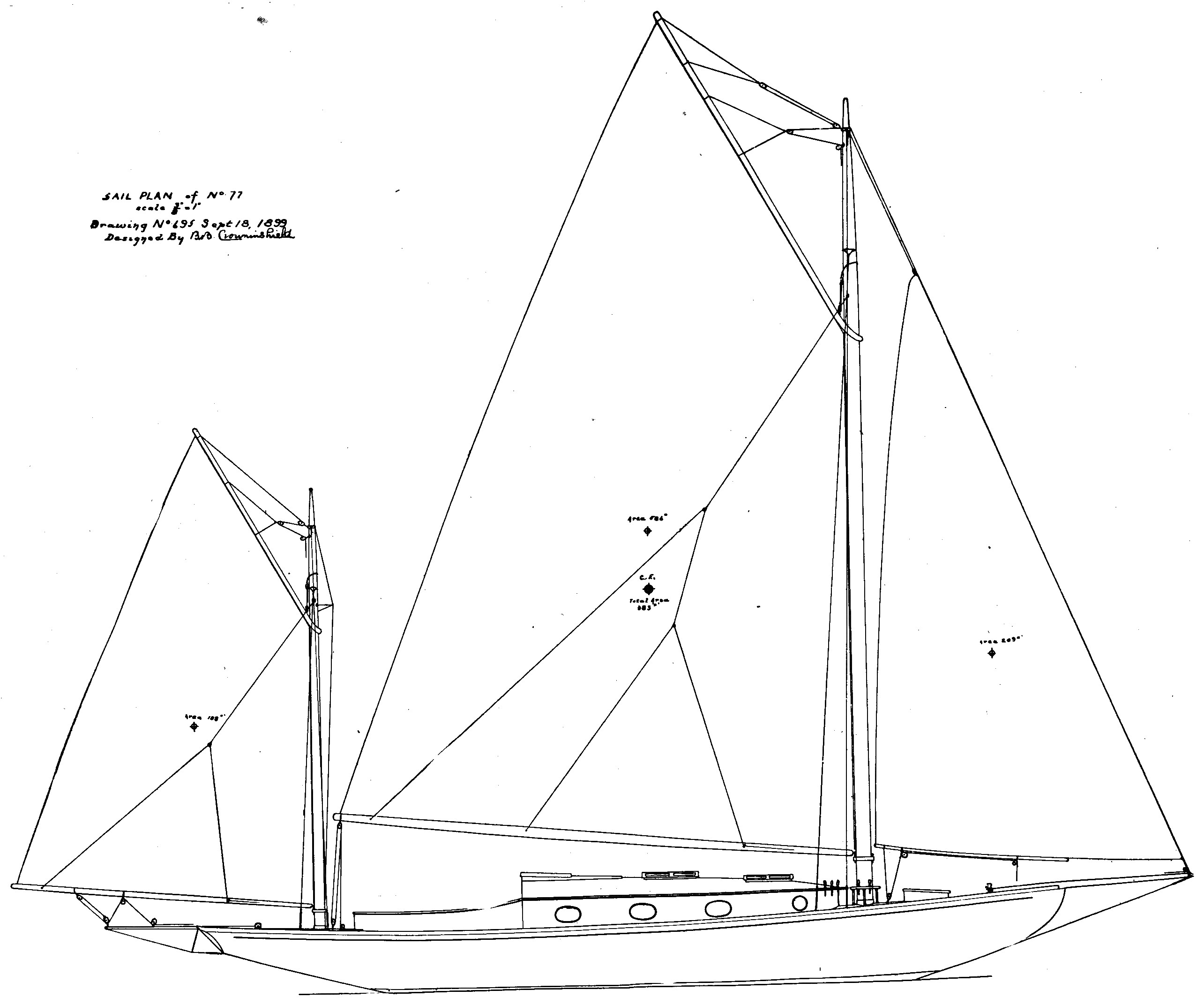
Auxiliary cruising yawl
designed by B.B. Crowninshield, 1899
The problem of placing the engine in an auxiliary is one that has been worked out in a great many different ways, and yet it is always a difficult one to solve. In most cases the boat is made very full aft in order to get the engine or motor, as the case may be under the cockpit floor. This necessarily makes the boat slow under sail, and also places the machine in such close quarters that it is difficult to get at the various parts in order to give them the necessary care and attention.
The plans given here came through the kindness of designer Bowdoin Bradlee Crowninshield (October 13, 1867 – August 12, 1948), his design No 77, as follows:
| Length overall | 41' 1" |
| Length waterline | 25' 0" |
| Overhang forward | 7' 2" |
| Overhang aft | 8' 11" |
| Freeboard stem | 4' 2" |
| Freeboard stern | 3' 0" |
| Freeboard minimum | 2' 8" |
| Draught extreme | 4' 0" |
| Draught to rabbet | 1' 11" |
| Displacement | 15,369 lbs |
| Outside ballast | 5,000 lbs |
| Inside ballast (engine) | 1,800 lbs |
| Beam at waterline | 10' 8" |
| Beam extreme | 11' 8" |
| Sail area | 983 square feet |
They show a departure from the usual way of solving the question in that the design of the boat is the same as it would be if the question of power were wholly left out, and the engine instead of being squeezed in under the cockpit is located in the after end of the cabin in a nicely arranged little engine room. This arrangement necessitates two companionways, one entering the cabin and one the engine room, which is entirely shut off from the cabin, so there can be no possibility of any odour, and the noise of the engine is greatly reduced. Of course some room is lost in the cabin, but it is still large enough to get sleeping accommodation for four persons, plenty of lockers, and a toilet room and galley forward, with still room enough for a man before the mast. This boat is being built for Mr. Lawrence Witcomb by Murray and Tregurtha, of South Boston, who are also makers of the motor she will carry.
Line drawings
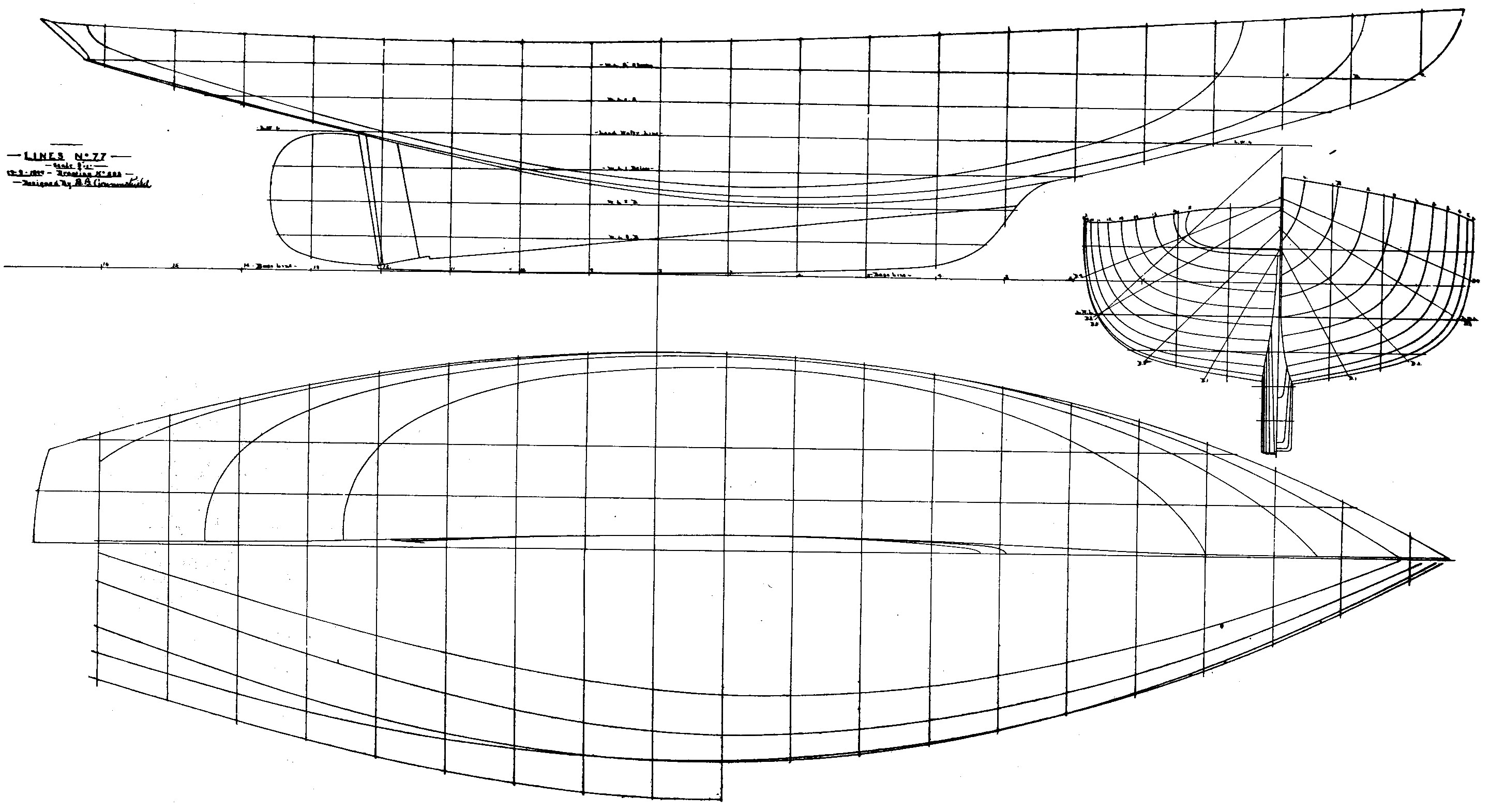
In the plan view, Mr Crowninshield shows the diagonals in the bottom half, This was normal practice at the time, and shows a rather flat exit aft, considered to be conducive to speed and efficiency.
Cabin arrangements
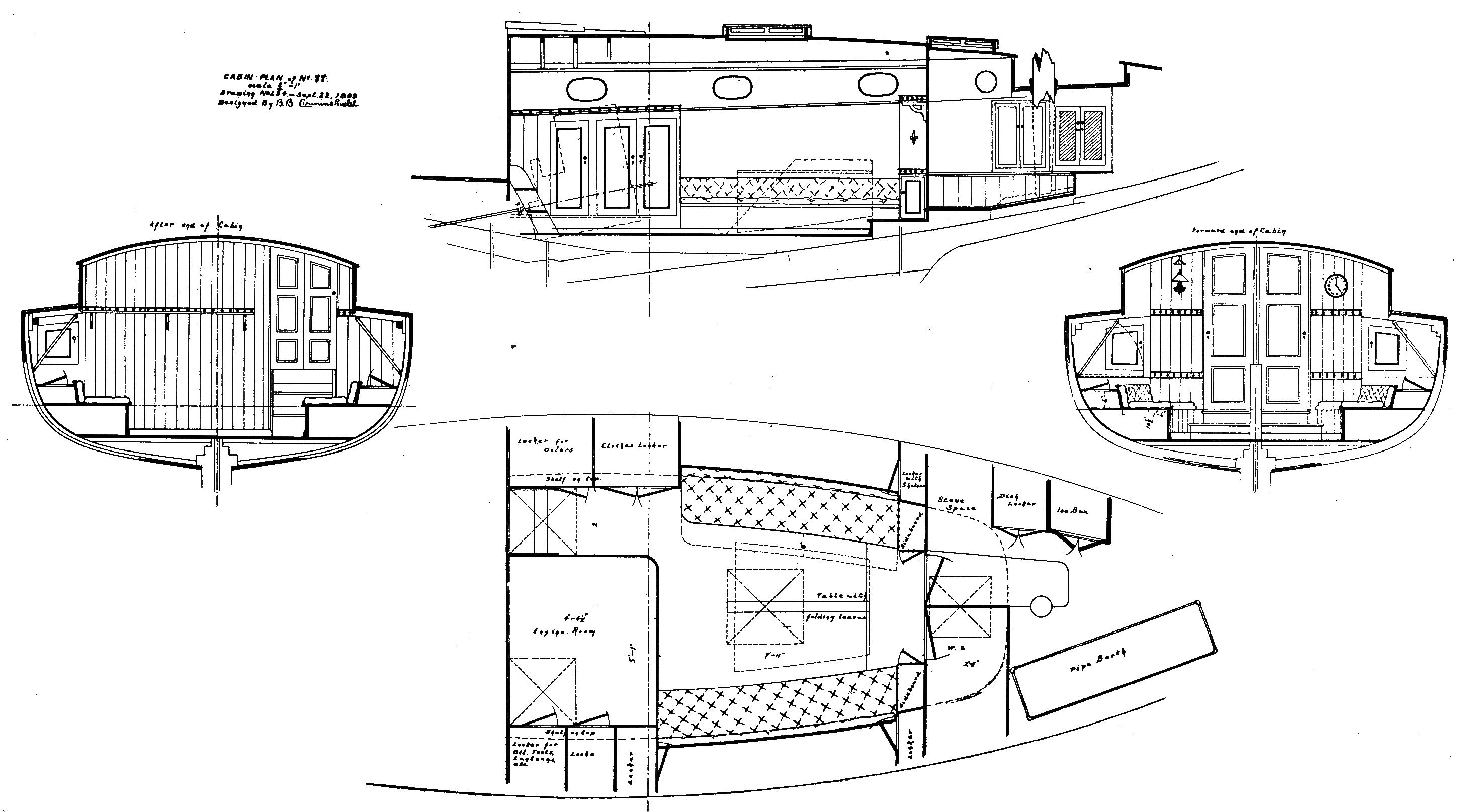
Note that this plan is numbered 88, not No 77 as the others. [Editor's note: there is a suggestion here that Mr Crowninshield was considering a centre-board or other form of drop-keel. The lines above, show very little lateral plane, probably leading to excessive leeway when beating to windward. We have not been able to verify the boat, as built for Mr. Lawrence Witcomb by Murray and Tregurtha. PA]
This page is adapted from an article in the Rudder Magazine of February 1900.