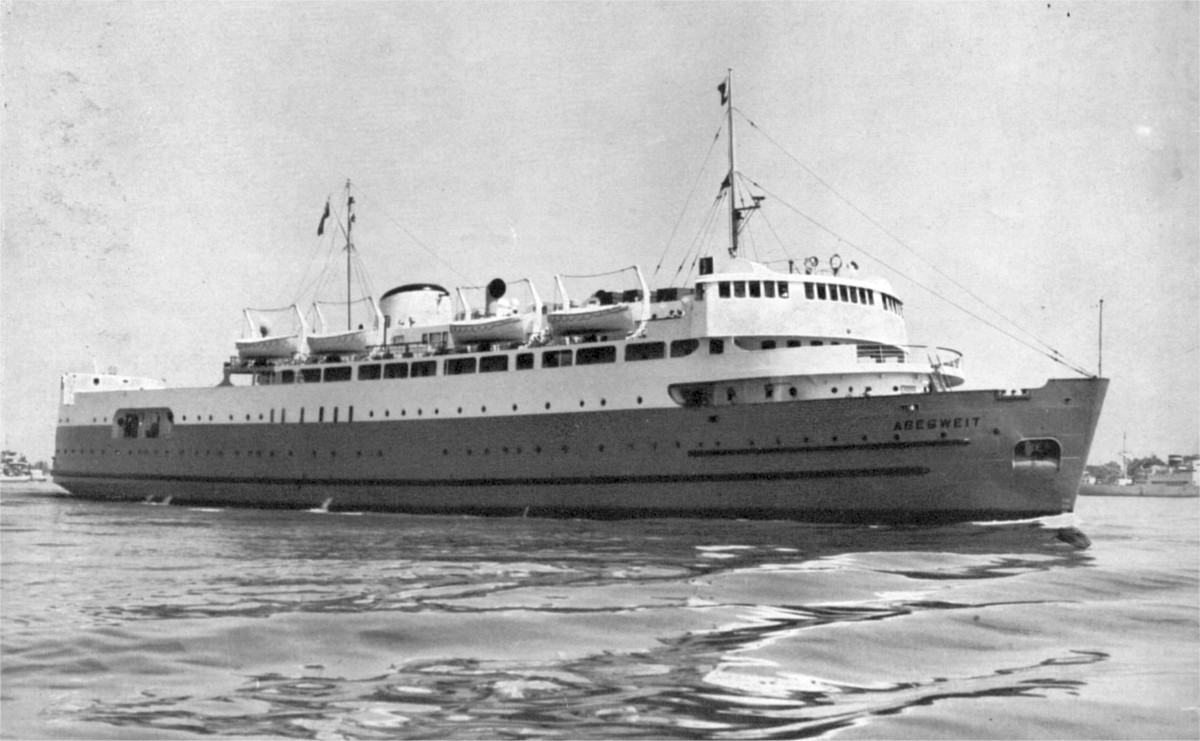
M.V. Abegweit Prince Edward Island Car Ferry
by H.H German, M.E.I.C.,
German and Milne, Naval Architects and Marine Surveyors, Montreal
A paper delivered before the Montreal Branch of The Engineering Institute of Canada on December 4, 1947
The invitation from your Council to present a paper on the Icebreaking Car Ferry Abegweit was an honour indeed, although the difficulties in determining the form such a paper should take were realized. There are unusual technical features in this ship which would be interesting to a gathering of naval architects and marine engineers, but which perhaps would lack interest for the members of this Institute. However, after due consideration and some advice from fellow members, it was decided that the paper should be more descriptive than technical.
As the history and development of the Prince Edward Island service was dealt with in a paper on the Charlottetown, given before the Institute in 1932, it is not proposed to repeat this, except as is necessary to give those present a clear conception of the strides made in the communication and transportation systems between the Island and the rest of Canada since the days of the early settlers.
History of Early Ferry Service to "The Island"
The initial venture to establish communication with the mainland was undertaken in birch bark canoes which plied between Wood Island and Pictou as far back in 1775. Later came the flat bottomed dories operated by two men, and fitted with runners which enabled them to be pulled over the ice. The next step was an adaptation of the Norwegian "pram" or ice boat, used as late as 1916, despite other means of communication evolved.
In 1832 the first attempt was made to put a steamer into service, and the Pocahontas, a vessel of wooden construction, made the trip between Charlottetown and Pictou twice a week, followed by the Albert in 1873, and the Northern Light, a steam icebreaking vessel of wood construction in 1877. The Northern Light did not prove as successful as was hoped and she was superseded by the Neptune, a wooden Newfoundland sealer, after which the Lansdowne entered the service.
In 1888 the Federal authorities, who were now responsible for maintenance of service as a result of the stipulation in the Island's agreement to enter Confederation, placed the newly constructed steel ice breaker Stanley in service, to be succeeded eleven years later by the Minto and in 1909 by the Earl Grey. Each of these was an improvement on her predecessor, although frequent and prolonged interruptions in the winter service were still experienced. The type of ice breaker so successful in operation in fields of sheet or solid ice, having a sloping icebreaking bow, proved quite ineffective under the ice conditions. The Stanley was built along such lines, but the shape of the bow merely assisted her to cut a channel through the obstruction. On such occasions it was a major operation to get the ship back into the water.
The Minto had a different type of bow, designed with the idea of trying to overcome the defects of the Stanley. The same difficulties were encountered, however, as despite the increased power, great trouble was experienced in freeing her from the ice, the operation sometimes taking as long as two days.
The Earl Grey proved to be a decided improvement; she was fitted with rounded sides and her increased power gave her greater flexibility in backing and filling, at the same time permitting her to work with speed in and out of the icefields. Although the rounded sides made it difficult to dock at the terminals, all in all she proved to be a good icebreaker for this service. She was, however, not the final answer to the problem as a whole. The time required for the trip was too long, and considerable produce was spoiled while held up at the terminals and on account of the unsuitable carrying conditions on the ship.
The chief factors responsible for the development of the service from 1915 onwards were the perishable nature of the Island's produce and the impossibility of developing and maintaining trade relations with the outside world under the then existing conditions. Careful and exhaustive study by the Federal authorities of the many and varied problems attendant on the service finally resulted in a steel icebreaking railway car ferry, the Prince Edward Island, in 1915, to operate between Port Borden and Cape Tormentine, a distance of approximately eight miles. The new vessel was not as efficient as the Earl Grey as an icebreaker. Although she was built with about the same power per ton of displacement, she lost efficiency by being more wall-sided.
The Charlottetown, built in 1930-31, was a manifest improvement over the Prince Edward Island. Her sides were rounded, and her steam installation was as powerful as possible consistent with the size of her hull. The design of this ship was also influenced by the rapid growth of the automobile trade, which exerted a profound effect on the development of the service. The unfortunate loss of this ship in 1041 occurred at a crucial time and, despite the wartime curtailment of shipbuilding for other than naval purposes, plans were made to relieve the crisis which would confront the Islanders when commerce and travel would revert to a pre-war basis with every possibility of rapid growth. The ultimate result was the construction of the Abegweit, which entered the service in August 1947.
Requirements to Be Met by Designs
The essential qualifications for a ship operating in Northumberland Straits and maintaining year round communication are iceworthiness, speed, dependability and rapid, efficient manoeuvrability.
There were many interesting but perplexing problems to be faced in determining the size and general characteristics of this ship. The situation was rendered more difficult since she had to fit the existing terminals, which restricted her length, breadth and operating draft. Consideration was given to the building of new terminals to suit the most efficient design of ship. When it became evident, however, that any changes to existing terminals would mean a long period without safe and adequate service, it was decided to design to suit the existing terminals, as this could be done without much loss of time, at the expense, however, of obtaining the ultimate in ship design.
The harbours at Cape Tormentine and Port Borden are extremely difficult to approach and navigate with such a large ship, but the operation to date of the Abegweit indicates that the fitting of four propellers has proved to be a great success, and docking is decidedly easier than with her predecessors.
Little reliable information is available on ice conditions. There are many variables to contend with. Ice formations encountered in the St. Lawrence River, Northumberland Straits, the various harbours of Canada, Hudson's Bay and the Arctic vary to such a degree that an efficient icebreaker for one service would be useless elsewhere. The strength of ice varies from a maximum for clear solid ice to practically zero for slush or frazil ice. In our Canadian lakes, bays and harbours we have sheet ice to contend with, varying from minor thicknesses to as much as three feet in the Great Lakes. For such conditions the design of a ship is simple, but with the broken ice that is swept up and down Northumberland Straits by winds and tides, and packed at times solid to a depth of thirty feet, the characteristics of an ice breaking car ferry for this service must be quite different to those of the average icebreaker.
An analysis of the service from the time of its inception indicated the desirability of packing as much power into the hull as practicable. It called for a type of power which would permit the greatest flexibility of operation. Other requirements were maximum horsepower per cubic foot, and minimum weight per given power. Also needed was an increase of the torque of the propellers, with a decrease in revolutions to permit the maximum propeller thrust with the ship operating in heavy ice. Conversely the greatest thrust was demanded with the ship operating at zero speed. Lastly, rapid transference of power from the bow to the stern propellers, and vice versa, was essential. The answer to all these requirements was unquestionably diesel electric machinery.
The design of the Abegweit parallels the development of U.S. Coast Guard Service vessels patrolling the ice lanes. Practically all these vessels are equipped with diesel electric machinery. The latest mammoth units in this service are powered with multiple diesel engines operating three propellers in lieu of four as on the Abegweit. As these vessels have to operate in the far north, far from repair bases, where utmost reliability is required, it is significant that they are fitted with multiple diesel engines with electrical transmission.
Passenger Accommodation
In addition to housing a complement of sixty-five officers and crew with adequate lounge spaces, all in accordance with latest I.L.O. requirements, the public rooms will seat about 250 day passengers, while emergency sleeping accommodation is provided for about 100 passengers. Seats are also provided on decks. The ship has a Passenger Certificate from the Canadian Board of Steamship Inspection for 950 persons. A higher than average standard of comfort has been provided, first to attract tourist travel to the Island, and secondly to offset the discomfort to passengers if the vessel becomes icebound for any length of time.
Accommodations have been fitted out to a standard comparable to modern passenger liners. The layout of the restaurant meets with the special requirement of serving one hundred passengers in half an hour in the space available. The most modern equipment and labour saving devices have been installed for this purpose, and the restaurant is fitted with stainless steel counters and shelves. Refrigerated compartments for perishable foods are installed, the refrigeration being of direct expansion type throughout in association with pipe coils.
Propellers and shafting
The development of the bow propeller is a point of interest. In the case of the Saurel and Ernest Lapointe, two icebreakers engaged in the St. Lawrence service, it was discovered that they were more efficient at times when operating astern, backing into the ice with the two stern propellers, than when going ahead. This fact, and the success in service of the bow ice-breaking propeller on the Prince Edward Island and the Charlottetown, led to the decision to fit four propellers on the Abegweit — two forward and two aft.
The greatest precautions were taken in the design of the propeller and shafting installations, particularly the bow propellers, which are subject to severe shock when entering either solid or broken ice. Allowance was made when the thrust blocks were designed for a generous margin of safety, over the normal thrust to be expected in the shafts when working in open water. When considering the shock resulting on entering an ice jam, it was decided the thrust block should be capable of absorbing a direct thrust of 125 tons, in association with propeller revolutions of 25 per minute. These blocks are comparable in size to those fitted on a vessel of approximately the same power as the Queen Elizabeth. Shafting was specially designed to take this thrust and journals were fitted to suit.
The propeller design was complicated, and an efficient compromise had to be arrived at in order to achieve the following results: that the pitch, diameter and area would be such that the full developed power on any one shaft could be absorbed in the propellers at full speed in open water; that the propellers would prove efficient in cutting ice; that the propellers would be sufficiently strong to absorb the impact and pressure when operating in ice, but not so strong that the blades would not be broken rather than the main shafting when operating at low revolutions against heavy resistance of ice, all within the limits of torque prearranged by the amplidyne settings; that the propellers be of sectional type with an arrangement for adjustment of pitch; and that the propellers be efficient in both directions, the pitch being the same on both sides of the blade, which permits machining and a nearer approach to statical and dynamical balancing.
The propellers are of cast nickel steel — two percent nickel. The intermediate shaft diameters forward and aft are 16 in., and the shafting material is high grade forged steel, which is necessary to keep the tailend or propeller shafts to a minimum diameter. This in turn permits a minimum propeller diameter for the same efficiency, which is somewhat contrary to normal ship propeller design. This is a necessary compromise in this case, as it puts the propellers at the lowest possible point below the waterline, away from the region where blades are most likely to be damaged when striking blocks of ice. The propeller tips have been kept a minimum distance from the shell of the ship. The distance is necessary to prevent jamming of ice blocks between the tips of the propeller and the hull of the ship.
The Hull
The conditions prevailing in Northumberland Straits call for a more efficient service than is usually required of the average icebreaker. An uninterrupted service on an exacting schedule is the prime requisite. Such service entails serious wear and tear on a ship's structure, and it was not uncommon in previous vessels on this run to find them at times literally being kept afloat at the end of the winter season by their internal watertight subdivisions. Many years ago the policy of repairing by welding rivets and seams was adopted which decreased maintenance cost. This, together with the outstanding performance by smaller icebreaking vessels of all-welded construction, dictated the policy of designing an all-welded structure. Maintenance of the hull of the Abegweit will cost considerably less than that of her predecessors on this account. Parts of the shell plating are 1 1/8 in. thick and the size and weight of the ship greatly in excess of any vessel previously built in Canada.
Shell plating was fitted flush on the moulded or inner surface, and varying thicknesses of plates were taken up on the outside. All seams and butts of shell surfaces were specially prepared for welding, the thickest plates requiring more than twenty passes with 3/16 in. welding rod. No welding was carried out at temperatures below 10 deg. F. Pre-heating was resorted to at all temperatures below freezing. About a million feet of welding was done, involving 260,000 man hours of labour and 250,000 lbs. of Stelco welding rod. The efficiency of the welding was tested and constant use made of radiography to determine the quality of the work.
To meet requirements of iceworthiness the ship was designed and constructed to withstand contact with ice when using maximum power under way. Horizontal compression loading was taken at not less than 24 tons per linear foot at the waterline. The ship was constructed on the transverse framing system. Substantial transverse web frames were fitted throughout, with longitudinal deck girders and stringers to support the transverse frames. All framing was reinforced by a system of bulkheads, sufficiently strong to serve as main compression units. The scantlings were determined on the basis of the bulkheads being adequate to withstand flooding to 8 ft. above the main deck, added to compression loads due to the railway car deck carrying its full complement of cars.
The maximum of subdivision has been provided for, even beyond the legal requirements for passenger ships. Protection of the machinery spaces is increased by double bottom compartments and full depth side tanks below the car deck. At the fore and after ends of the engine rooms and between the engine and motor room spaces, watertight doors are fitted in bulk heads for protection against flooding. All necessary openings have watertight doors with local and wheel house control for their automatic operation in an emergency. All openings in the shell were kept to a minimum. Overboard discharges have been specially designed for a ship operating in ice. The main circulating seachests are fitted with hot water returns from the main engines, so that frazil ice can be kept clear by the hot water. Complete de-icing arrangements have been fitted, and all important outlets have hot water or steam connections. A supply of hot water is provided for hosing down the decks.
Railway Equipment and Automobile Cargo
Of almost equal primary importance to icebreaking efficiency is the ability to carry railway passenger and freight cars, motor trucks, automobiles and passengers. Railway officials, bound as they are by normal railway schedules, are not altogether sympathetic to the tourist whose object is to get his automobile on and off the ship. The passenger who wants comfort in his living quarters is usually more concerned with the restaurant service. On the Abegweit a successful compromise appears to have been effected between these somewhat conflicting services.
The railway car deck was designed to withstand live loads incidental to the carrying of a light T4A Canadian National engine with an allowance for impact. Due to the varying deck spans, apertures, pillar supports, etc., strength calculations were made for every deck beam. A great variety of sections was used so uniformity of strength could be maintained without sacrificing too much material. The automobile deck was calculated to withstand the loading of large trucks and buses with maximum live wheel load plus an additional allowance for impact.
As well as electrically driven capstan windlasses for the normal operation of the anchors, the ship is fitted with two electrically driven capstans on the main car deck for hauling railway cars to the car buffers. Two additional capstans are fitted aft to handle the lines while docking. These after capstans are also used to haul the ship close to the shore apron. Electrically operated screen doors are fitted at the after end of the car well, for use during winter operations.
Heeling, Trimming and Steering Equipment
Large capacity heeling pumps are installed, capable of handling 423,000 gallons per hour, to transfer water between wing tanks on either side with despatch. Transference of this water will heel the ship 10 degrees each side of the vertical in one and one-half minutes. A trimming tank is also provided, and a pump having a capacity of 3,130 gallons per minute is fitted in the forward end of the ship. This permits adjusting the depth of the forward propellers below the water line to suit prevailing ice conditions. The pump and tank are connected with an 18 in. pipe, all valves being motor operated with remote control in the navigating bridge. Large air relief valves are needed to avoid excessive pressures on the divisional bulk heads and crowns of the tanks.
The operating staff use the engines almost exclusively for manoeuvring in the harbour, yet there are occasions when this has to be supplemented by the rudder. The weight of the rudder is over ten tons, and it can be locked in the centre position when the ship is backing and filling in ice. It is activated by an electro-hydraulic four-ram steering gear specially built for icebreaking service, operated by a 45 hp. d.c. motor which will put the helm from hardover to hardover in twenty-four seconds with the vessel at full speed. It can be operated by the quartermaster through a telemotor system either from the navigating bridge forward, or from the docking bridge aft.
Safety and Control Equipment
Nothing has been spared to guard against fire hazards; the machinery spaces can be flooded throughout by carbon dioxide in the event of fire, and the battery of storage bottles can be operated locally, or by remote control from the bridge. A complete fire detection system is operated from the bridge. Life saving arrangements and equipment are complete in every respect and in conformity with the latest Canadian Steamship Inspection requirements.
The vessel is heated by auxiliary steam boilers automatically controlled, one in each engine room. On all exposed surfaces of the spaces requiring heat, adequate insulation, generally in the form of asbestos sprayed on the steel structure, has been applied to keep the expense of maintaining a warm ship to a minimum and to eliminate excessive heat in summer. A system of ducts permits the ship to be heated by heat recovered from the machinery spaces. Ventilation is of the latest type on the forced air supply system, controllable both as to quantity and temperature by the engineer.
The most modern navigational aids have been installed, including gyro and magnetic compasses, echo sounding machine, ship-to-shore radio-telephone and radar. Remote control of the propelling motors is fitted both in the navigating and docking bridges. All operating controls have been combined in neat compact console-type control cabinets. It is not necessary to ring telegraphs from the bridge to attract the attention of the engineer, as with previous ships. Direct operation of the motors is carried out by the navigating officer, during the delicate operation of docking and undocking, and in attacking ice formations. This feature should result in a lower maintenance cost in the elimination of errors in judgment, or delayed operation between the master and the engineer.
Numerous protective devices and alarm controls have been incorporated, to render the ship as safe and trouble-free as possible, such as water and lubricating oil alarm and control, fuel oil control, over speed control, maximum motor field strength control, overload control of engines, watertight door control and fire protection; all have been made as foolproof as the most up-to-date practice permits. Modern and complete engineers' and electricians' workshops and stores are provided to facilitate routine repairs and adjustments without recourse to shore repair shops.
Engines and Propulsion Equipment
The arrangement of machinery on this ship is somewhat unusual, inasmuch as each main propulsion set consists of a twelve-cylinder 1,500 B.H.P. engine, divided into two banks of six cylinders each with the generator mounted between them, and the whole is supported on a common welded steel bedplate of specially fabricated design. This bedplate is in turn welded to the tank top of the ship, since it was decided that any deflection in the tank top, even though transmitted through bedplate to crank shafts, would come within the allowable deflection for crankshafts, and would not prejudice the safe performance of the machinery.
The engines, generators, motors, shafting and propellers on the starboard side form one complete propelling system, while similar equipment on the port side constitutes another complete system. The main propulsion is of diesel electric direct current type with amplidyne voltage control of field excitation. speed and reversal of the propulsion motors. The propulsion equipment comprises four shafts and propellers, two forward and two aft, each with their own propelling motors capable of transmitting individually 3,850 shaft horsepower aft or forward, or, when operating uniformly, giving a distribution of 2,500 shaft horsepower per propeller. Motors are remote controlled from the navigating bridge, the docking bridge or the engine control room. Either one of the port propelling motors can be connected to one, two or three of the port generating sets, and similarly for the starboard units.
The main power supply is from eight twelve-cylinder Dominion Sulzer TS-29 type fresh water cooled diesel engines, direct connected to a generator. The engines are rated to drive the generator at full output continuously, with ten percent overload for two hours, and twenty percent overload for fifteen minutes. The engines are of the vertical compression ignition air starting full diesel type. Air for combustion can be drawn from the engine compartment, or from the atmosphere. Thus better control of engine room temperatures can be maintained, an important item for electrical equipment, particularly when wide ranges of atmospheric temperatures are encountered. Standard starting controls were furnished with each engine and fuel control stops were provided to prevent dangerous overloading. Governors and governor control equipment were furnished, an independently driven overspeed governor was fitted to each engine.
The temperature of the engine cooling water is thermostatically controlled on each engine. Fresh water is used, and the heat exchangers can operate efficiently with sea water at a maximum temperature of 65 deg. F., while the maximum temperature of the fresh water leaving the engine water jackets is arranged not to exceed 130 deg. F. Thermocouples were furnished for each individual cylinder exhaust outlet for use with permanently installed temperature dial indicators.
The engines are equipped with a barring device for turning the engines by hand. Indicator cocks are provided on each cylinder for attaching a maximum pressure indicator, so that proper adjustment of engines can be readily maintained. Engine controls are mounted on each engine, including an emergency shut-down device.
Electrical Equipment
Three 330 kw. auxiliary engine generator sets are provided for the auxiliary machinery, two in the forward, and one in the after engine room. Air is drawn from the engine compartment. Also, for emergency and port use, two 60 kw. diesel generating sets are provided in a compartment above the load water line at the railway car deck level. All auxiliary services are supplied at 225 volts direct current.
The electrical equipment consists of two separate systems or installations; that pertaining to the main generators, propulsion motors, switchboards and controllers for propulsion and manoeuvring of the ship; and that for supplying power for the exciters, motors, pumps, lighting distribution, switchboards, etc.
The main propulsion generators are rated at 1,050 kw., maximum voltage of 325, at a speed of 360 rpm., designed for continuous duty at 35 deg. C. ambient air temperature, for a temperature rise by thermometer of 75 deg. C. in the core and windings, 85 deg. C. bare copper windings and 90 deg. C. commutator. They are totally enclosed with separate ventilation and separate excitation, built on a split frame with a forged flanged shaft having shunt wound commutating windings. The insulation is class "B", suitable for 1,000 volts to ground. They are cooled by air forced through an enclosed system with precautions against damage through leakage in the air cooler. The air cooler medium is salt water. Alarm circuits are provided in case the generator gets too hot.
The propulsion motors are of the single armature type, designed to absorb the rated horsepower of the shaft at any speed between 128 and 155 rpm. propeller speed, and to be capable of delivering 150 per cent full load torque momentarily at creeping speeds, with a suitable protection device to prevent commutator damage in the event of actual stalling. Each propulsion motor has the following characteristics:
- Shaft Horsepower - - 3,850
- Speeds - - - - - - - 128 to 155 rpm.
- Voltage- - - - - - - 960 Maximum
The other characteristics are identical to those of the generators.
The motor bearings are of the pedestal self-aligning type, arranged for flood lubrication with adequate oil seals to prevent the rotor fouling the starter if the bearing is wiped. The motors are provided with carbon dioxide fire extinguishing systems to permit the flooding of the interior air circulating systems in the event of fire.
Switchboard and Controls
The control platform, located on an elevated sound proof enclosure in the forward engine room, contains the propulsion control systems. The control panel boards consist of two L-shaped deadfront semi-steel enclosed units, housing the various distribution and control switches. A number of relays for transfer and signal purposes are used, but the main speed and reversing control does not require any moving parts, static devices being used throughout. Main field and protective contactors do not operate except when generators are being switched. All arrangements are designed to operate the control systems without any moving parts as far as practicable, to minimize maintenance.
Propulsion generator and motor speed controls are maintained by an amplidyne system, operating on the general fields, with five amplidyne sets, one being a spare. Each set includes a motor, generator and amplidyne exciters and is driven by a direct current motor. Protection is provided in the circuits against overloading the engines. A number of other protective features are incorporated, such as electric overload and short circuit protection. The speed controllers have ahead and astern motions. Reversing is accomplished by reversing the amplidyne field connections on the amplidyne controlling the generators. This is done without breaking the circuit, by means of a potentiometer connection.
All connections between the propulsion generators and the switchboards are made with solid copper busbars in lieu of cables, in view of the high voltages and the uncertainty of the ambient temperatures of the engine room. The installation of these connections to suit the practical layout of the ship happens to be in the hottest part of the engine room, with no predetermined means of arriving at possible temperatures to be expected. This feature was the cause of much thought while design details were being worked out, and it is believed to be the first time such an extensive busbar installation has been used in a ship.
The horizontal runs are made of two 4 in. x 1/2 in. copper bars per polarity spaced 1/2 in. apart. They are enclosed in a wire mesh trunk having a mesh sufficiently fine to exclude rats, and mounted in slotted arborite boards with clearances to allow for possible deflection of the car deck. To permit longitudinal movement resulting from expansion or contraction due to temperature changes, laminated copper joints are provided, with suitable glands at watertight bulkheads. Vertical runs from the generators are made from two 6 in. x 1/2 in. copper bars per polarity, insulated for 1,000 volts. Busbars carry 3,200 amps at 960 volts continuously, or 6,400 amps for short periods.
Feeders from the switchboards to the propulsion motors consist of four single core 1,250,000 circular mills basket weave armoured steel braided cables per polarity, suitable to permit free air circulation.
The auxiliary power is distributed from a three-panel generator switchboard to a twenty-circuit enclosed distribution panel, both located in the control room. All air circuit breakers installed on feeders are capable of interrupting 2,500 amps, available under short circuit conditions.
The operating controls are basically developed around the amplidyne system controlling the motor speeds. At each of the three control stations, duplicate control cabinets are installed, one for the motors of each side. These cabinets are fitted with Selsyn telegraphs, indicating lights, speed indicators and alarm systems, and are arranged to make the necessary changes in the motor generator set-up, and automatically allow these changes to be confirmed. By means of transfer switches the greatest flexibility is provided, so that either one of the control positions can be used without fear of signals being transmitted from the other stations. With this complete installation the ship can be operated in a variety of ways in service, and with several combinations of engines. She is thereby equipped for the four very diverse but major operations of running in free water, manoeuvring at the terminals in open water, manoeuvring at the terminals under ice conditions, and operating between ports in any ice conditions.
The electrical work throughout the ship is extensive for, in addition to the motors described, there are one hundred and thirty-five auxiliary motors complete with all necessary power and lighting systems. Approximately 100,000 feet of electrical cables of different sizes, varying from two to sixteen conductors per cable were installed. In all there were about 200,000 man hours of electricians' labour worked into this ship, which may be termed a ship operated by push buttons.
A Credit to Canada's Shipbuilding Industry
The vessel was built to obtain the British Corporation Register of Shipping and Aircraft's highest class for an icebreaking railway car ferry, operating in field and pack ice. She had also to comply with the highest requirements of the Canadian Board of Steamship Inspection. Her size, her design, and the material and labour problems attendant on her construction were a severe test of Canadian initiative and ability.
The successful achievement has no doubt raised the prestige of Canadian shipbuilding. It is a matter of pride to all concerned with the Abegweit that she is practically one hundred percent a Canadian accomplishment, excepting a few auxiliaries from Britain, and the amplidyne control equipment manufactured in the United States.
Great credit is due the shipbuilders for their willingness to undertake such an important and exacting contract, which from the welding point of view alone would have taxed the facilities and resources of any large British shipyard. Credit is due also to the manufacturers of the machinery and electrical equipment, to the Canadian Board of Steamship Inspection, to the operating staff of the Canadian National Railways, the British Corporation Register of Shipping & Aircraft, the suppliers of the various items of equipment, and to the operating personnel of the ship, particularly Captain J. R. B. Maguire, and to Commander C. R. Edwards of the Department of Transport who took the responsibility for providing the best and most modern ship possible for the service, and who is to he sincerely commended for his vision and co-operation.