A steam catapult installation
Lieutenant-Commander K. B. Denison, R.N., A.M.I.MEcH.E.
Introduction
In July, 1953, there appeared in the Journal (Vol. 6, No.3) an article by Commander W. R. Stewart entitled "The Steam Catapult" which described the evolution of the slotted cylinder mechanism, its use in the B.S.4 steam catapult, and the installation of the equipment in a ship. The purpose of this article is to describe more fully a steam catapult installation in a ship and to show how those fitted in H.M.S. Ark Royal have behaved for the first six months of their operational use.
H.M.S. Ark Royal is the first operational carrier in the Royal Navy to be armed with steam catapults, two of which are fitted, each with a nominal stroke of 151 feet. The ship recently completed her first year in commission, over six months of which were spent operating with squadrons embarked and, since commissioning, the catapults have, between them, made 3,195 'live' launches (i.e. not including dead-loads).
The installation
In the following descriptions of the major items of the installation, it is assumed that the reader has already read Commander Stewart's article and is familiar with the slotted cylinder as it applies to the B.S.4 catapult. Seee Fig 1 for a section.
|
Fig. 1: Section through a B.S.4. catapult Click for enlargement. |
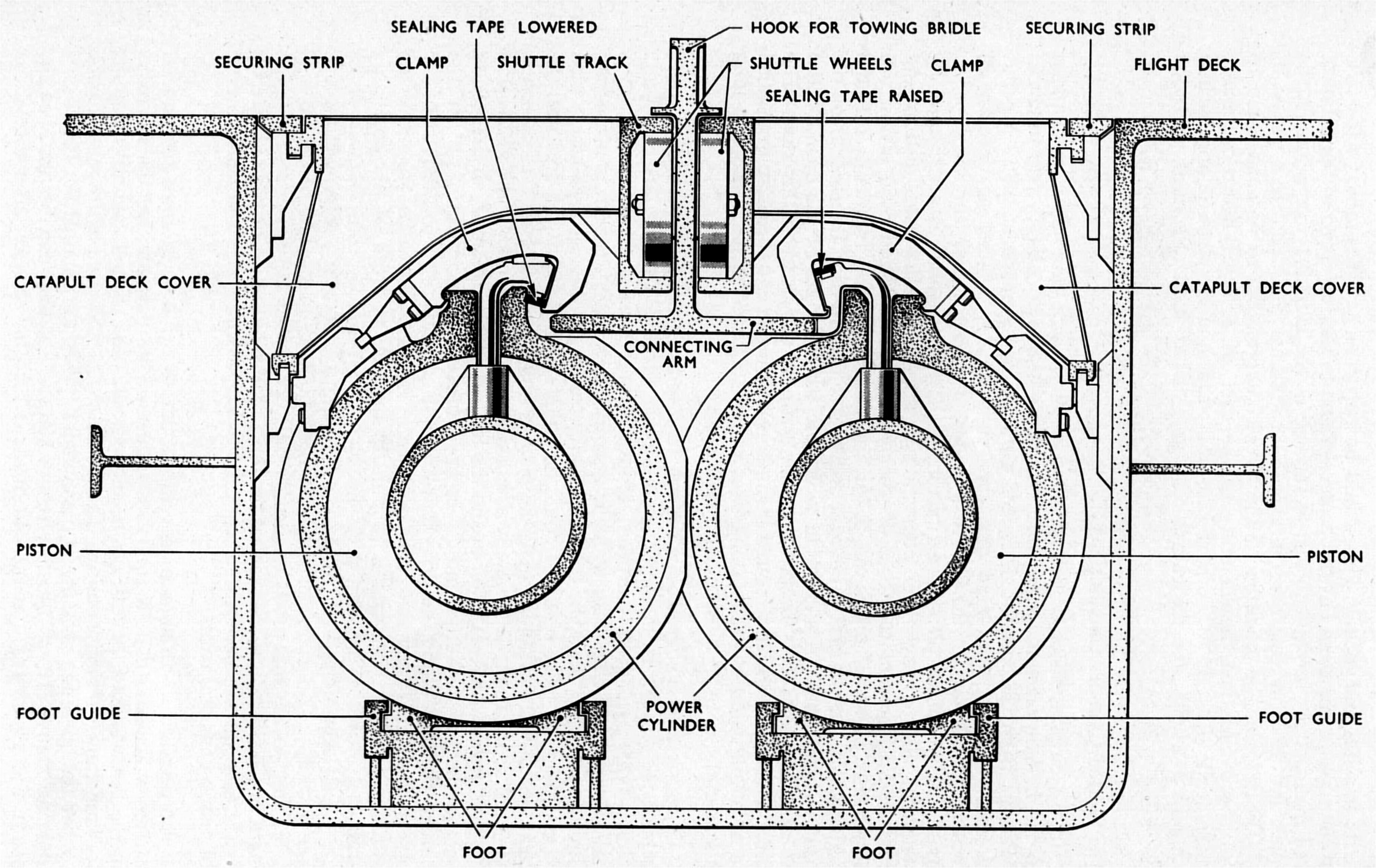
The Piston Assembly
This consists of two pistons in each cylinder connected to a shuttle by means of dogs on the driving key, which allow relative movement in the vertical plane only. Each pair of pistons consists of a driving piston at the after end carrying piston rings, a guide piston connected to the driving piston by a distance piece and, on the forward end, the retardation ram. The driving key is connected to the distance piece, and passes out of the cylinder through a gap made by lifting the sealing strip locally.
The shuttle is simply a trolley, with four pairs of wheels running in the track, carrying the towing hook.
The Retardation Unit
The retardation unit is composed mainly of a pair of cylinders, each open at the forward end, and placed at the forward end of each of the catapu1t cylinders. At their after ends are nozzle rings with nozzles set tangentially and inclined forward, through which water is sprayed into the cylinders. A horizontal vortex of water is thus formed in each cylinder, the water striking the closed end and returning through the centre of the vortex, thus keeping the cylinder full. The water then flows back into the tank from which the retardation pump takes its suction. The pistons are retarded by the rams entering the cylinders and ejecting the water between them and a choke-ring in the cylinder, the annulus through which the water passes getting smaller until, at the point of rest, it is practically closed.
The Sealing Strip
This is of rectangular cross-section and is manufactured in mild steel. It is lifted in way of the driving key and then moved back into its seat to provide the pressure seal for the cylinder, and in spite of the frequent flexing it receives, it does not seem to have suffered unduly after six months operation.
The Jigger
The pistons and shuttle are completely free to move fore and aft in the cylinders and track, and are not connected in any way to the ship's structure. Therefore, some method of manreuvring and retracting this assembly must be made. This is done by fitting a trolley (the' grab ') in the catapult track abaft the shuttle, the hook of which can latch on to a pin secured to the after end of the shuttle. The grab is manrœuvred by securing it to two pairs of wires, one pair running round the forward end of the catapult (the acceleration wires) and one pair running aft (the retardation wires). The other ends of these wires are connected to a 16/1 rope and sheave system, the moving crosshead of which is connected to a double-acting hydraulically operated piston. Hydraulic fluid at 4,000 lb/sq in to operate the jigger is supplied by an air-loaded accumulator (the jigger or main accumulator) which is kept charged by a steam driven hydraulic pump. The whole rope system is kept under tension by means of lazy sheaves, to prevent the wires whipping as they pass round the sheaves.
On completion of a launch with the pistons at the forward end of the catapult track, pressure is applied to the acceleration side of the jigger, and the grab moves forward until its hook latches on to the shuttle. Pressure is then applied to the retraction side of the jigger, and the grab tows the shuttle and pistons to the after end of the catapult track. Control of this fast movement of the grab, up and down the track, is by means of a cam operated valve in the console, which will be described later.
Tensioning an aircraft prior to launching is carried out by applying and maintaining hydraulic pressure to the acceleration side of the jigger by a small solenoid operated valve in the deck edge control position. When the catapult is fired, the shuttle breaks away from the grab leaving the grab behind with its hook cocked, ready to latch on again after the launch.
Using the tensioning valve, which operates the jigger slowly, the shuttle can be moved to any part of the catapult track for examination and maintenance. For harbour use, when large quantities of fluid are not required, and at sea when in the stand-by condition, a small motor driven hydraulic pump is fitted to keep the accumulator charged.
Cylinder Lubrication
The cylinder bores are lubricated by injecting small quantities of oil at a number of points along the length of the cylinder and cylinder cover before each moving forward and retraction of the pistons. The lubricators are operated by L.P. air and are controlled automatically by a cam-operated valve in the console.
|
Fig. 2: Arrangement of a B.S.4 catapult in an aircraft carrier Click for enlargement. |
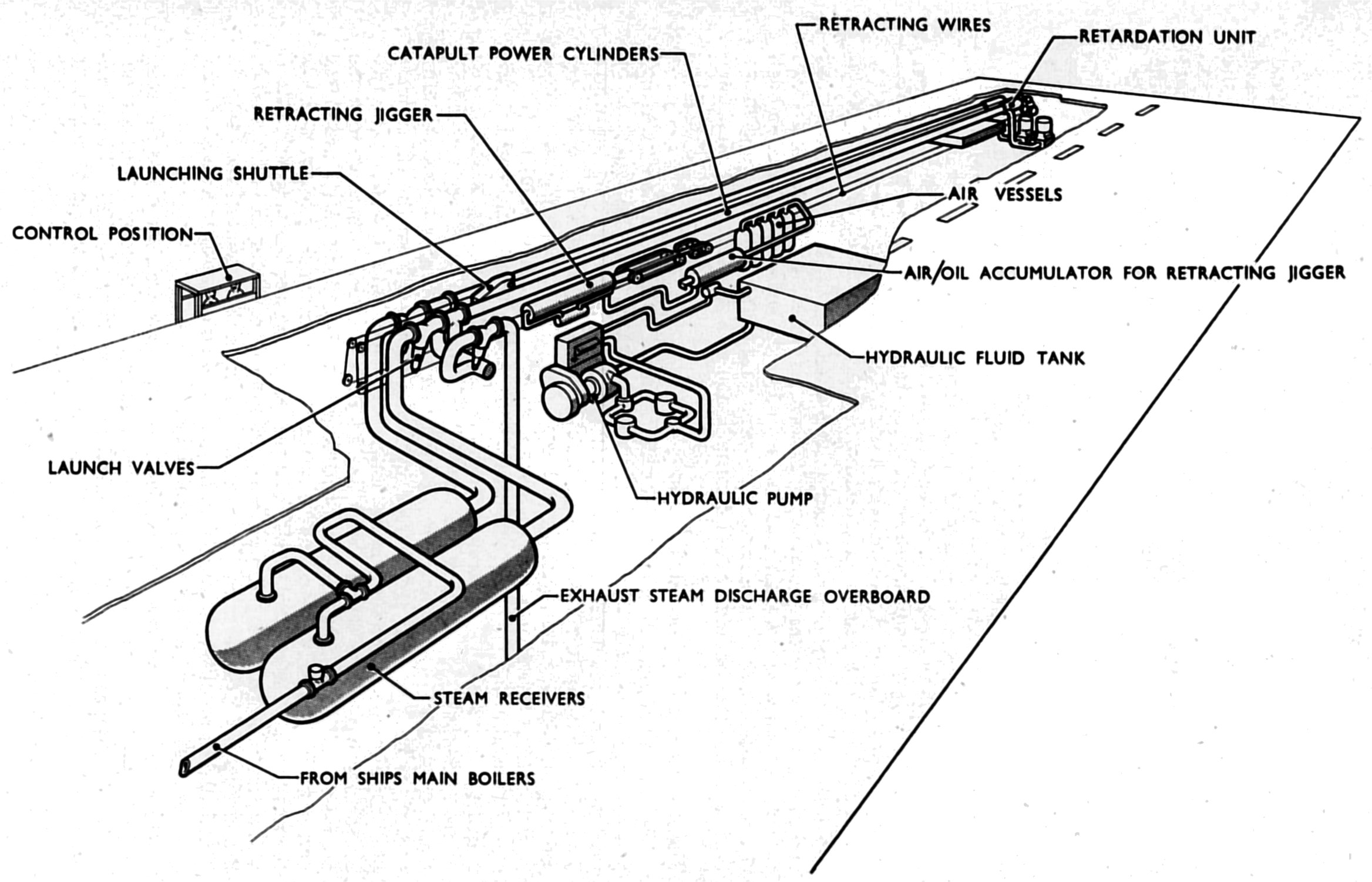
The Steam System
The steam system can be seen in Fig. 2. The purpose of the launching valves is to admit steam from the receivers to the cylinders, thus carrying out a launch. Their rate of opening is controlled in such a way that the max/mean ratio of the acceleration of the shuttle during a launch is as near as possible to unity. The opening of these valves is most important as their mal-operation can have a disastrous effect on the performance of the catapult. Therefore, before each day's catapulting, and after any work has been carried out which could in any way affect the operation of these valves, their current functioning is recorded on a time-displacement recorder, and the diagram obtained compared with a standard diagram.
The exhaust valve, on completion of a launch, is opened to allow steam in the cylinders to be discharged overboard.
There are two launching valves per catapult, one to each cylinder, but the exhaust lines are married, and only one exhaust valve is necessary. All three valves are controlled automatically by cam-operated valves in the console, hydraulic pressure, at 2,500 Ibjsq in being supplied by a separate air-loaded accumulator which is kept charged by the main pump
.Steam is supplied to the receivers from the ship's boilers and blown down to sea. The flow control valve and the blow-down valve are hydraulically operated and are fitted to increase or reduce, respectively, the steam pressure in the receivers, a Duplex pressure gauge being sited in the console. They are controlled by hand from the console.
To prevent excessive steam consumption, a butterfly valve (the steam cut-off valve) is fitted between each launching valve and cylinder. These are also hydraulically operated, controlled by steam pressure acting through a port which is uncovered by the piston when it has travelled about two-thirds of the way along the cylinder. Release of steam pressure from the cylinders allows the valves to open.
Warming Through
To prevent excessive condensation of steam (thus losing some of the energy in the steam) in the cylinders when launching at the beginning of the day, the cylinders are warmed through by admitting steam through small pipes by-passing the launching valves, until the expansion of the cylinders is of the order of 1½ in. which is about the minimum for launching with catapults of the length fitted in Ark Royal.
Expansion of the cylinders is permitted by anchoring the units immediately abaft the launching valves and allowing the cylinders to expand forward, the cylinders resting on pads in the trough, not bolted to them. The forward cylinder length slides over the retardation cylinder which is also anchored to the ship's structure.
Interlocks
A number of interlocks are fitted, some to ensure correct functioning of the gear before and during launching, others to prevent damage to the gear. The following are the major interlocks which must be made before the catapult can be fired :-
(ii) Retardation cylinders full
(iii) Launching valve accumulator charged
(iv) Steam cut-off valves open.
Their correct operation should all show lights in the console, and if any light is not showing, the catapult cannot be fired. Other interlocks are fitted so that :-
(b) The catapult cannot be fired until the safety chocks are down
(c) When two catapults are fitted in a ship, only one can come to the 2nd ready at a time (see later).
End-Speed Recorder
An end-speed recorder is fitted to measure the speed of the shuttle at the end of a launch. A magnet, carried on the forward end of the shuttle, imparts a signal to two coils placed a few feet apart at the forward end of the catapult track. The time interval between the two signals is converted, by an electronic machine in the machinery compartment, into speed in knots which is read off and recorded. The end-speed recorder is an invaluable aid in checking the performance of the catapult, especially over a long period of time, and has proved very reliable.
Operation
Control Positions
The catapult is controlled from two positions, the console, which is situated in the catapult machinery room just below the flight deck, and the deck edge control position (or' howdah ').
The console operator sits before a desk on which are the two main control levers operating the catapult :-
(b) The receiver pressure control valve.
The controller moves in steps, and with it the cam shaft which operates the various cam-operated valves already referred to. All the cams are connected rigidly to this shaft except for the launching valve cam which moves with the shaft for all steps of the controller except the last prior to firing. At this step, the launching valve is held stationary against the action of the spring, when the catapult is said to be 'cocked'. When the fire-button is pressed, a solenoid moves the catch and releases the cam, thus opening the launching valves.
The howdah operator controls the chocks, positioner roller mats, tensioning and the firing of the catapult. In both the console and the howdah there is a 'cancel' push which can be pressed at any time, up to firing, rendering the catapult safe, if the operator detects anything wrong or the F.D.O. raises his red flag.
The sequence of operations, assuming that a launch has just been completed, is :-
(b) When the indicator, showing the position of the grab in the track, shows the grab to be right forward, the controller is moved the second step, retracting the grab, thus towing the piston assembly aft.
(c) Meanwhile, the console operator is re-charging the steam receivers to the correct launching pressure. When this is complete, he closes the flow control valve.
(d) The next step of the controller closes the exhaust valve and injects oil into the cylinders.
(e) With the correct receiver pressure, and all the interlock lights burning, the 1st ready push is pressed by the console operator, a white light showing in the howdah and on the flight deck.
(f) Meanwhile, the aircraft is being loaded, and when it is tensioned correctly, and the 1st ready light is showing, the howdah operator presses the 2nd ready push, which shows a green light in the console. (g) When he sees the 2nd ready light, the console operator finally checks his gauges and moves the controller the last step, cocking the catapult. He then presses the final ready push which shows a red light in the howdah and on the flight deck. (h) When the final ready light is showing, the howdah operator lowers the safety chocks, and then, when the F.D.O.'s green flag drops, presses the 'Fire' push.
End-Speed Control
Control of end-speed of the steam catapult, as it is operated in H.M.S. Ark Royal, is by the variation of the initial receiver steam pressure alone. Broadly, the variables involved in calculating receiver pressure required for a given end-speed are :-
(b) Aircraft thrust – Assumed constant for each type of aircraft.
(c) Expansion of catapult cylinders – Measurable and requiring a correction to the steam pressure.
(d) Temperature of hydraulic oil operating the launching valves – Measurable, but can be kept constant.
|
Fig. 3: Curves showing end-speed / steam pressure relationship, |
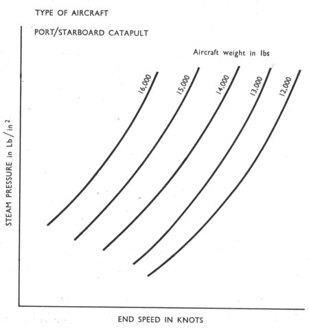
Fig. 3 shows the form of curves made out for each type of aircraft and for each catapult, having been drawn using results of flying trials. The curves are made out for a cylinder expansion of 2 inches and correction for expansion is allowed for by adding or subtracting 3 knots to the end-speed required for each inch of expansion down or up respectively. A set of these curves covering all types of aircraft carried, and liable to be carried in the ship, is held by the F.D.E.O.
Before a series of launches, the F.D.E.O. obtains from Flyco the types of aircraft to be catapulted, their weights and the end-speeds required. Then, knowing the cylinder expansion he can calculate the steam pressure required; this information he passes on to the console operator.
Variations of End-Speed
In practice, while it has been found in Ark Royal that, whereas end-speeds actually obtained have generally agreed very closely with those calculated, under certain conditions they have disagreed.
The first two or three launches of a day's flying, when the catapult has not been used for, say, 12 hours or more, have been below the calculated figures (i.e. corrected for expansion), the first launch being as much as 4 to 6 knots slow. The end-speed of the first launch of a series, when the catapult has been idle for only an hour, is usually about 2 knots below the calculated figure.
At the other end of the scale, when launching large numbers of aircraft, say, 20 aircraft in one series, the cylinder expansion rapidly rises to .about 3 inches, and then remains steady, but the end-speeds continue to increase, and have reached up to 5 knots in excess of the calculated figure.
Though these variations cannot be predicted accurately, they can be anticipated by increasing or decreasing the steam pressure 10 to 20 lb/sq in for the first launch and the last few launches respectively. This has worked quite satisfactorily in Ark Royal and end-speeds have been fairly consistent.
Light Launches
A 'light' launch is one without any load on the shuttle. To prevent excessive end-speeds, which may damage the retarding mechanism, the initial receiver pressure must be low, and for the catapults in Ark Royal, 100 lb/sq in is used. Because of this and the fact that the break-out load is low (that between the grab and shuttle only being of the order of 8,000 lb) the steam pressure-does not build up in the cylinders, and at first it was thought that this might leave the sealing strips slack in the cylinder heads, thus allowing them to become damaged. Admiralty permission had, therefore, to be obtained to carry out a light launch, and this was granted only in exceptional circumstances. However, recent trials in H.M.A.S. Melbourne have shown that this is not the case, and permission has been given to carry out light launches in certain circumstances.
In Ark Royal they have been carried out :-
(b) Mter the correction of a failure of an interlock or some vital part of the launching mechanism when a light launch would restore the confidence of the pilots.
(c) After work on the end-speed recorder, which will not record below 50 knots.
(d) When the first launch of the day is required to be as fast as possible due to the undesirability or inability to obtain any wind along the deck, and a series of light launches will thorougly warm through the cylinders.
PERSONNEL
The personnel manning one catapult is :-
1 C.E.R.A. or Ch. Mech. – In general charge of catapult, and in particular controls loading aircraft.
2 M.(E)s – Bridle numbers.
1 L.M.(E) – Hold back number.
1 P.O.M.(E) – Howdah operator.
1 P.O.M.(E) – Console operator. 1 E.R.A. or Mech. – In general charge of machinery.
1 L.M.(E) or M.(E) – Hydraulic pump watchkeeper.
1 M.(E) – End-speed recorder.
1 M.(E) – Retardation pump watchkeeper.
In Ark Royal, except for the retardation pump watchkeeper, who looks after both pumps because they are sited together, the crews are the same for each catapult. The ship's complement allows for only one C.E.R.A. to control the loading of both catapults, but this has been found impossible because of the high rate of catapulting with the steam catapult. For round-the-clock flying in two watches, the number of officers and ratings, shown above, are doubled. The large amount of electrical gear in the control and interlock systems has made the almost full-time services of an E.A. invaluable.
LAUNCHING INTERVALS
The design launching interval for the steam catapult was 30 seconds per catapult and, in Ark Royal, this has been attained. Individual intervals have been as low as 29 seconds, and using two catapults, a mean interval of 15½ seconds for 12 aircraft has been achieved.
The breakdown of times (in seconds) for an individual interval of 31 seconds is :-
First movement to grab engaged – 10
Grab engaged to start retraction – 1
Start retraction to shuttle fully aft – 8
Shuttle fully aft to signal forward tension – 0
Signal forward tension to fully tensioned – 2
Fully tensioned to F.D.O.'s flag up – 4
F.D.O.'s flag up to down flag – 4
Modifications to the jigger hydraulic system during the present refit will, it is hoped, reduce the grab movement times by 4 seconds, and it is considered that, with good pilots allowing fast aircraft loading, the overall time could be reduced by the same amount.
Defects
Only some of the major defects, their causes and possible cures, that have occurred during Ark Royal's first operational six months will be mentioned. A number are basically design faults of a type that would be expected when testing prototype machinery operationally for the first time, but others are due to bad installation of the machinery and these could have been avoided. Some are predictable and can be dealt with during a period in harbour, but the majority are not and the first indication is that the catapult is U/S. This is not only infuriating for the catapult crew, those on the flight deck and bridge, but tends to give the steam catapult a bad name, especially when representatives of the Technical Press are present for a demonstration.
Premature Break-Outs of Aircraft
The hold back anchor of a B.S.4 catapult is fitted with a liquid cushion to prevent the aircraft from being brought up 'all standing' as it taxies into it. During flying trials after commissioning, it was found that this cushion was too soft and was 'bottoming', causing the breaking rings to break prematurely. A Sea Hawk nose wheel liquid spring was fitted in series with the cushion and this has worked very well.
Grab Break-Outs
With the retraction speed of the grab set to its maximum, it was found that the shuttle was frequently being left at the forward end of the catapult track during a series of launches, the grab having broken out from the shuttle. The grabs needed frequent refitting, and tended to distort badly, affecting the breakout load. But it was noted that the break-outs occurred even with a recently refitted grab. Some measurements were taken to determine, in actual practice, the towing loads involved, and the figures were rather revealing.
Split up into the three measurable components, they are :-
| Load in lb: | Maximum | Minimum |
| Friction | 1,400 | 1,000 |
| Acceleration | 4,000 | 2,800 |
| Back pressure | 3,100 | 2,600 |
| Total | 8,500 | 6,400 |
The maximum load that can be set on the grab hook is 8,000 lb which leaves little or no margin.
As an interim measure, grab retraction was slowed down and the number of break-outs was greatly reduced. Meanwhile, a newly designed grab is being produced which, it is hoped, will soon be available for fitting.
Piston Wear
During a routine examination, it was discovered that the guide pistons had worn beyond allowable limits, and required renewal, This involved removing the retardation cylinders and piston assemblies complete, a very large job. The driving pistons were found to have worn a similar amount and were also replaced. When catapulting recommenced, measurements of rate of wear were taken, and it was calculated that the life of these pistons was only 700 to 800 launches.
During investigation, it was found that the cylinder lubrication was not working correctly, and in spite of all efforts by the ship's staff, the best that could be obtained was 50 per cent of the lubricators working. It is proposed to improve the method and increase the quantity of the lubrication.
The main cause of the wear was considered to be steps in the cylinders caused by machining tolerances of the cylinder sections. These steps have now been honed out.
Piston Cracking
When the pistons were first removed because of wear, the driving pistons of the starboard catapult were found to be badly cracked round the flange which secures the piston to the distance piece. After exhaustive investigation, the cracks were attributed to a very fast retraction of the grab, allowing the pistons to strike a spigot at the after end of the cylinder track. One and a half inches were machined off the skirts of the replacement pistons, and no further cracks have been found.
Jigger Wires
While launching a series of aircraft, the shuttle of the port catapult stopped suddenly during retraction, about half way down the track. Investigation showed that the wire had stranded, the resultant coil jamming the wire in one of the sheaves. Examination of the other wires revealed wear and corrosion, in spite of frequent greasing, and all the wires were renewed. It is considered that the failure of the wire was caused by the hemp core charring under the considerable heat to which it is subjected, thereby allowing the lay of the wire strands to distort. New wires with a wire core are to be supplied and, to prevent corrosion, they will be galvanized and provided with automatic lubrication. Had a complete break occurred on the acceleration wires where they pass through the bottom of the trough, their replacement would have been a very big job, and it would probably have been necessary to lift the catapult cylinders to re-reeve new ones. The wires are, however, now being led outside the trough and this difficulty will be avoided.
Tensioning
Tensioning of aircraft has never been completely satisfactory because of the poor design of the solenoid-operated valve. The valve frequently locks hydraulically and the solenoid is not strong enough to operate it. This results in erratic tensioning loads. It is hoped that a valve of new design, recently fitted, will effect a cure.
Chocks
One effect of an hydraulic failure was discovered when a small pipe burst on the port catapult during the loading of an aircraft. The hydraulic pump was stopped and the main accumulator blown down. In the general confusion it was not realized that the safety chocks were still up, fouling the angled deck, preventing a land-on. The pump was re-started and sufficient pressure obtained to lower the chocks, the loss of fluid being accepted. To prevent a recurrence of this incident which might well have been more serious if the burst pipe had been large and pressure could not have been maintained, a hand pump will be installed to lower the chocks in an emergency.
Miscellaneous
A large number of defects have been minor in themselves, but have occurred so frequently, that the operational efficiency of the ship has been affected.
They include :-
(b) Faulty working of interlock warning systems, especially the retardation cylinder full interlock system
(c) Failure of steam joints, usually the inaccessible ones
(d) Failure of welds in hydraulic valve blocks
(e) Dirt and rust in hydraulic systems
(f) Failure and slackening of Unbrake bolts and Nyloc nuts.
The majority of these defects can be attributed to poor installation, and an early opportunity will be taken to try to remedy them by extreme care in the re-installation.
STEAM CONSUMPTION
The estimated steam consumption of a launch itself is about ¼ ton. Using this figure, that for overall daily consumption was estimated and, assuming a ten-hour flying period with two catapults in use and launching 6 aircraft each hour, it is found to be about 32½ tons, of which 7½ tons is used for warming through the cylinders. The steam consumption is nearly as high if the catapults are kept at immediate notice for the same period, the figure being 26 tons, of which 7½ tons is used for warming through, and over 8 tons for keeping the cylinder warm.
Modifications to the steam drain system which are being carried out will, it is hoped, save about 5 tons per day, and consideration is being given to carrying out light launches to warm through the cylinders, ten or so of which should be sufficient, at a steam loss of only one-fifth per launch.
Tactical
That the steam catapult is a big advance over the hydraulic catapults was successfully demonstrated when 16 Sea Hawks were catapulted while the ship was moored in Grand Harbour, Malta. There was only a very light wind, if anything, on the beam, and the end-speeds attained gave aircraft ample margin over their stalling speed, the breakwater being cleared without difficulty. This ability is of enormous tactical advantage as it means that aircraft can be launched long before the ship is into the wind, provided the cross wind component does not exceed 25 knots. At present, however, launching should not take place while the ship is heeled, though this was frequently done in Ark Royal with up to about 2 degrees of heel while the ship was turning into the wind. The Admiralty has been asked to relax this limitation as far as catapults are concerned in view of Ark Royal's experience.
Thus, the time the ship has to steam on a fixed course is limited only to the period for landing-on, reducing the risk to the ship and reducing the liability of having to steam out of her protective screen.
The other big advantage of the steam catapult is its low launching interval, a vital factor in these days of jet aircraft whose rate of fuel consumption is high. But the writer feels that a word of warning should be added here. Catapulting of the D.H.110 during recent flying trials was very successfully carried out, but the catapult was nearly 'flat out' and the aircraft was only about three-quarters of its operational weight. It is unlikely that this, or any other similar aircraft, could be launched with nil wind along the deck, ruling out the first advantage above, unless the stalling speed of the aircraft could be lowered. This means that the catapult imposes a limitation on the aircraft's performance, which is undesirable. The answer to this is that we should be fitting steam catapults with a longer stroke now, which would increase the end-speed without increasing the' g' on the aircraft. The U.S. Navy already has in service steam catapults of 2S0-foot stroke.
Conclusion
The first six months in Ark Royal has proved conclusively that the steam catapult is basically a very fine weapon. Some modifications will be necessary in the future to the ancillary equipment, and there have been many exasperating breakdowns and delays, but that is only to be expected with what is virtually, a prototype installation.